


INTRODUCTION
Thank you for your purchase of the ROLLS RA200 Power Amplifier. The RA200 is
a stereo 100 Watt per channel MOSFET power amplifier. It bridges to 200 Watts
into eight ohms. It is intended for professional audio applications such as record-
ing studios and small live performances.
INSPECTION
1. Unpack and inspect the RA200 box and package.
If obvious physical damage is noticed, contact the carrier immediately to make a
damage claim. We suggest saving the shipping carton and packing materials for
safely transporting the unit in the future.
2. Please complete the Warranty Registration Card and return it to the factory.
INSTALLATION
Connect the power cord to an AC power source, connect the input to the signal
source and to the RA200 via the RCA or 1/4” input jacks. Speakers may be
connected by using the 1/4” output jacks, or the dual banana posts. Turn the
Volume controls fully counterclockwise (off), and turn on the power switch, the
power LED should light. With the program material running, slowly increase the
Volume controls until the desired level of sound is present. There is a one second
turn-on delay provided to prevent possible speaker damage in case all equipment
is on a signal power strip.
MADE IN U.S.A.
RISQUE DE CHOC - NE PAS ENLEVER
SERIAL NUMBER
WARNING:
To reduce the risk of electric
shock or fire do not expose
this device to rain or moisture.
CHANNEL 2 INPUT
CHANNEL 1 INPUT
BRIDGE NORMAL
OUTPUT 2
OUTPUT 1
4A 120V - 2A 230 V
OUTPUT 1
OUTPUT 2
-
-
+
+
MAINS POWER
WARNING
For continued protection against
risk of fire, replace only with
same type and rating of fuse.
CAUTION
TO REDUCE THE RISK OF ELECTRIC
SHOCK DO NOT NOT REMOVE LID. NO
USER SERVICABLE PARTS INSIDE.
REFER SERVICING TO QUALIFIED
SERVICE PERSONNEL
C O R P O R A T IO N
BRIDGING
To bridge the RA200, first ensure the power is off. Move the Bridging switch to the
“Bridge” position. The Channel 1 Volume control will be the master volume,
Channel two Volume is inactive.
Connect the input to Channel 1 input, then connect the load (speakers) to the two
positive (red) banana jacks. Make no connections to the black posts. The level
meters will both light, and the output power into 8 ohms is the sum of the LEDs
that light.
FAULT PROTECTION
The fault protection in the RA200 limits the current to the output stage in the
faulted channel and turns on all the LEDs in that channel. This mode is entered
whenever the output stage is called upon for too much power, it may also be
fooled by impedances lower than four ohms - which may cause the output stage
to overheat and burn up the MOSFETs.
Since the RA200 is convection cooled, the unit radiates heat from the rear panel
and , depending on the load demand, it may become very hot if drawn upon
heavily.
SPECIFICATIONS
Power Output, Stereo: 100 Watts RMS/ch. 4 W
70 Watts RMS/ch. 8 W
Bridged - 200 Watts RMS 8 W
Input Connectors: 1/4" TRS balanced and RCA
Output Connectors: 1/4" and 5-way binding posts
Sensitivity: <1 VRMS for full output
THD: <.08% (1kHz @ 1 Watt)
S/N Ratio: 106 dBU
Power Bandwidth: DC - 30 kHz +/- 1dB
Damping Factor: > 150
Slew Rate: 100 Volts/microSecond
Phase Shift: <10 Deg., 20Hz - 20kHz
Input Impedance: 10 KW Balanced
Power: 120 VAC 60Hz 2.5A
230 VAC 50Hz
Size: 19” x 3.5” x 7.5”
(48 x 9 x 19 cm)
Weight: 12 lbs (5.5 kg)
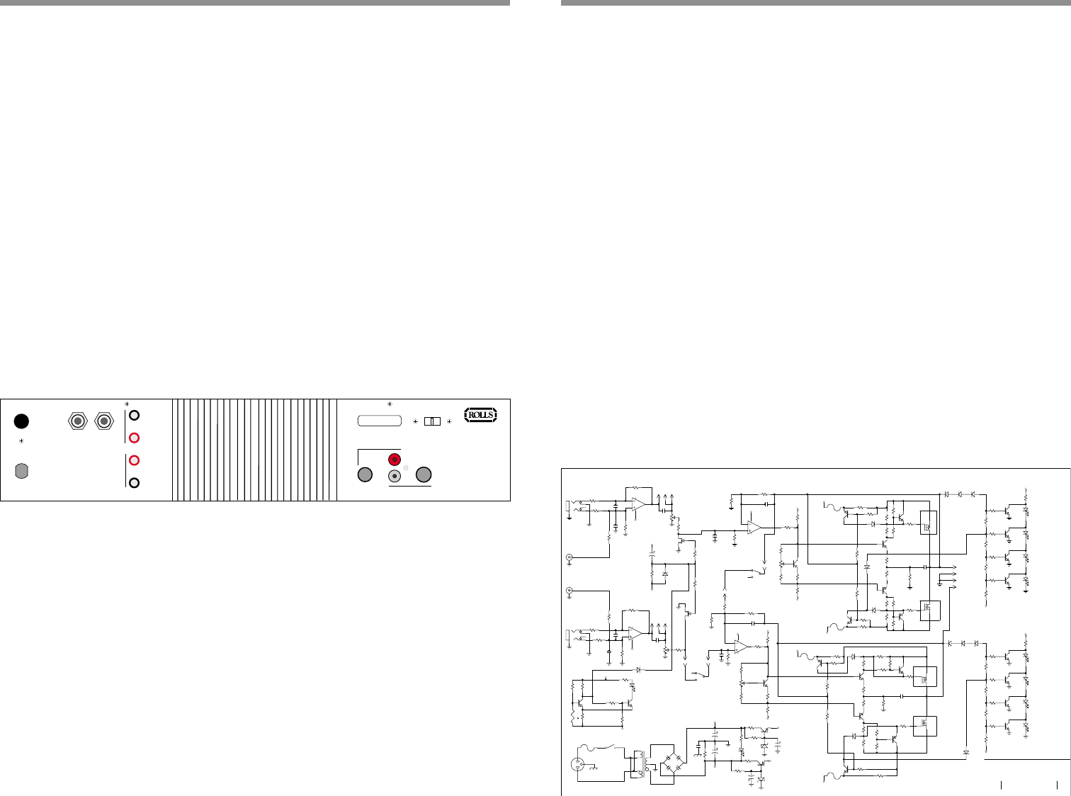
SCHEMATIC
1
ROLLS CORPORATION
5968 S 350 W
Murray, UT 84107
1
ra200.sch C
22 August 2002
Title
Size: Document Number:
Date:
Rev:
Sheet
of
RA200 Amp Board
Rb
Vr+
Vr-
V+
V-
Vr-
V-
V+
V+
HEATSINK
Vr-
Vr+
Vr+
Vr-
Vr+
Vr-
V-
V+
V+
HEATSINK
Vr-
Vr+
V+
V+
1
5
32
100
1
5
32
100
LAST R72 C15
12V
-12V
BRIDGE
NORMAL
Vr+
CHANNEL 1
CHANNEL 2
SET P2 & P102 FOR 1 - 2 mV ACCROSS R11 & R111
Vr+
Vr-
PROTECT
4
1
3
2
BR1
CP8010
SW1
SW SPST
J1
J2
J3
PLUG AC MALE
R1
10K
R2
10K
Q4
MPSA06
Q1
J113
D4
1N4148
D5
1N4148
D6
1N4148
D2
1N4148
D3
1N4148
R15
10K
P1
P100K
1
23
1
2
3
P101
P100K
4
5
6
SW2B
DPDT
Q2
2N3904
Q3
2N3906
D1
1N4148
4
H1D
1
2
3
SW2A
DPDT
5
H1E
Q5
2N3904
P2
500
Q11
2N3904
Q12
2N3904
Q13
2N3904
Q14
2N3904
D7
LDRY
D8
LDRG
D9
LDRG
D10
LDRR
F4
6A
1
H1A
2
H1B
6
5
7
8
U2B
1458
6
5
7
8
U1B
1458
2
3
1
4
U1A
1458
2
3
1
4
U2A
1458
F3
6A
F2
6A
F1
6A
F5
4 AMP
T1
MAINS TRANSFORMER
1
H4A
HD42
H4B
HD43
H4C
HD44
H4D
HD4
R3
1K
R4
33K
R5
33K
R6
1K
R7
100K
R8
470
R9
10K
R10
1K
R11
10K
R12
6.8K
R13
1K
R14
150
R16
150K
R17
150K
R18
.1
R19
470
R20
1K
R21
10K
R22
2K
R23
22K
R24
51
R25
330
R26
330
R27
100
R28
2K
R29
22K
R30
470
R31
.1
R32
1K
R33
10K
R34
51
R35
10K
R36
10K
R37
100K
R38
10K
R39
100K
R40
10K
R41
100K
R42
33K
R43
10K
R44
10K
R45
1K
R46
33K
R47
33K
R48
1K
R50
470
R52
10K
R55
6.8K
R58
10K
R59
150K
R60
150K
R61
.1
R62
470
R63
2K
R64
330
R65
1K
R66
22K
R67
10K
R68
51
R69
330
R70
100
R71
2K
R72
1K
R73
22K
R74
10K
R75
51
R76
470
R77
.1
R78
10K
R79
10K
R80
100K
R81
10K
R82
100K
R83
10K
R84
100K
R85
33K
R89
470
R91
10K
R92
1M
R93
3.3K
R94
22K
R95
1K
R96
10K
D11
1N4148
D12
1N4148
D13
1N4148
D14
1N4148
D15
1N4148
D16
1N4148
D17
LDRY
D18
LDRG
D19
LDRG
D20
LDRR
R98
1K
R99
10K
R100
4.7K
Q6
IRF9540
Q7
2N3904
Q8
MPSA56
Q9
2N3906
Q10
IRF540
Q15
J113
Q17
2N3906
Q18
MPSA06
Q19
2N3904
Q20
IRF9540
Q21
MPSA56
Q22
2N3906
Q23
IRF540
R51
10K
R49
100K
P102
500
R56
1K
Q16
2N3904
R57
150
R53
1K
R54
10K
Q24
2N3904
Q25
2N3904
Q26
2N3904
Q27
2N3904
Q28
2N3904
Q30
2N3904
Q31
2N3904
Q32
2N3906
C1
.001
C2
470PF
C3
.01
C4
120PF
C5
50PF
C6
.002
C7
.001
C8
470PF
C9
.01
C10
120PF
C11
50PF
C12
.002
C15
10U
C16
10U
D21
RED
D22
ZD12V
D23
ZD12V
D24
LDRR
D25
1N4148
D26
1N4148
R102
4.7K
R103
1M
R104
1M
R105
1M
C17
1U
C18
503
R90
10K
R87
22K
R88
10K
Q29
2N3904
t
R101
THERMISTOR
C13
6800UF
C14
6800UF
1
H?A
HCN2
1
H?A
HCN2
1
H?A
HCN2
1
H?A
HCN2
1
3
J4A
RCAX2
2
3
J4B
RCAX2
Lo Cut
Lo Cut
10K@23c