


OPERATION
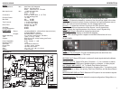
DIP SWITCH SETTINGS (From left to right)
• If a microphone requires phantom power, move the Mic channel’s correspond-
ing PHANTOM POWER switch to the up position. This applies 12 volts dc phan-
tom power to the indicated microphone.
• SOURCE 1 MONO; this switch sums the Right and Left inputs of Source 1 to
mixed dual-mono inputs.
• Mic 1 Priority; when in the up position, all program material on Mic 2 and Sourc-
es 2 and 3 will be “ducked” or muted when a signal is present at Mic 1. Source 3
is left un-muted.
This function is used for paging.
• Source 3 Priority: when in the up position, Source 1,and 2 will be “ducked” or
muted by the signals at Source 1.
This function is for jukebox priority. With a jukebox connected to Source input 1,
and the Talkover switch 2 on, the other Source input signals such as background
music, will be muted and only the jukebox will be heard.
• MONO / STEREO: When down, the output of the MA2152 is summed to mono.
Either jack can be used as a mono output.
FAULT PROTECTION
The fault protection in the MA2152 limits the current to the output stage. This
mode is entered whenever the output stage is called upon for too much power, it
may also be fooled by impedances lower than four ohms - which may cause the
output stage to overheat and be irreversably damaged.
Since the MA2152 is convection cooled, the unit radiates heat from the front
panel and, depending on the load demand, it may become very hot if drawn upon
heavily.
CONNECTION
Inputs
Connect low impedance microphones to the Mic inputs. If a paging microphone
is being used, connect it to Mic Input 1 so it may be used with the Talk Over
function. Connect source signals such as CD players, cassette players or video
players to the RCA Source Inputs. If a jukebox is being connected, and you want
its signal to mute the other source signals, connect it to Source input 1.
For recording purposes, connect a stereo RCA cable to the Record Out jacks,
and to your recording device.
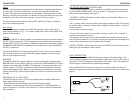
Amp Inserts
To connect a signal processor to the MA2152 signal(s), use an insert plug, or
cable wired as shown in Fig. 1. This return signal is then sent to the output level
section of the amplifier.
Outputs
In STEREO MODE, the Right speaker is connected to the red and black banana
RIGHT OUTPU connectors. The Left speaker is connected to the red and black
banana LEFT OUTPUT connectors. Impedances should be no less then 4 Ohms.
In BRIDGE MONO MODE, the speakers are connected to the two red BRIDGE
OUTPUT connectors.
Connect the MA2152 to a properly grounded AC outlet. There is a one second
turn-on delay provided to prevent possible speaker damage in case all equip-
ment is on a single power strip.
BRIDGING
To bridge the MA2152 outputs together, first ensure the power is off. Move the
BRIDGE switch to the “Bridge” position, and set the STEREO/MONO DIP Switch
(details on the next page), to MONO. The Channel 1 Volume control will be the
master volume - Channel 2 is inactive. Connect the load (speakers) to the two
positive (red) banana jacks. Make no connections to the black posts. The level
meters will both light, and the output power into 8 Ohms is the sum of the LEDs
that light.
DRIVING 25 OR 70 VOLT LINES
The MA2152 will drive 25 or 70 Volt lines directly with no added transformers
when used the following way:
- Each channel (used individually) will drive 25 Volt lines directly.
- A single 70 Volt line bay be driven when the MA2152 is in Bridged Mode. In
order to drive two 70 Volt lines, two 8 Ohms to 70 Volt conversion transformers
will be needed.
3 4
To Amp Insert
Fig. 1