


INTRODUCTION
Thank your for your purchase of the Rolls MA1705 Mixer / Amplifier. The MA1705 is a
single rack space mixer amplifier designed for restaurants, schools, churches, clubs etc.
The unit provides a compact and efficient way to mix up to three sources such as AM/FM
tuners, CD players, and video players with up to two microphones. Priority talkover is pro-
vided on Microphone Two for paging, and on Source One for a jukebox, telephone, etc.
INSPECTION
1. Unpack and inspect the MA1705 box and package.
If obvious physical damage is noticed, contact the carrier immediately to make a damage
claim. We suggest saving the shipping carton and packing materials for safely transporting
the unit in the future.
2. For warranty information, and to register your MA1705 warranty, please visit our web-
site at
www.rolls.com
and click on the Register Your Warranty Here button
.
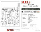
DESCRIPTION
FRONT PANEL
Treble
: Adjusts the high frequencies of the Source 2 and 3 signals only.
Bass
: Adjusts the low frequencies of the Source 2 and 3 signals only.
IN 1:
1/8” (3.5mm) Tip-Ring-Sleeve input jack - parallels the rear-panel Source Input 1.
Source 1 - 3
: Adjust the volume of input from the RCA Source Inputs.
Mic 1, 2
Mic 1, 2
: Adjust the level of signal from the corresponding Mic Input.
TONE 1, 2
TONE 1, 2
: Adjusts the frequency content of the microphone signal in the channel. When
the control is turned counter-clockwise, the high frequencies are cut, when the control is
turned clockwise, the low frequencies are cut.
Output Level
Output Level
: Adjusts the output level of the MA1705 amplifier.
Power
: LED indicating power is applied to the MA1705 and the unit is on.
Clip
Clip
. LED indicating overload in the MA1705 amplifier.
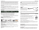
REAR PANEL
120 VAC 50/60 HZ 15 VA
120 VAC 50/60 HZ 15 VA
: IEC Power Cord. Connect to a properly grounded AC source.
NOTE: REPLACE THE FUSE WITH ONLY THE PROPER RATED FUSE. INSTALLING A
FUSE OTHER THAN THE RECOMMENDED RATING WILL DAMAGE THE UNIT.
OUTPUT
: Spring-loaded terminal for connection to the speakers.
OUTPUT: Spring-loaded terminal for connection to the speakers.OUTPUT
POWER AMP INSERT
: 1/4” Tip-Send, Ring-Return insert jack for.
POWER AMP INSERT: 1/4” Tip-Send, Ring-Return insert jack for.POWER AMP INSERT
MICROPHONE ONE and TWO
: Balanced XLR inputs to be connected to dynamic or
condenser microphones.
DIP SWITCH
: Contains the small switches for engaging Mic 1, 2 phantom power, and the
priority (Talk Over) functions.
SOURCE INPUTS
: Stereo RCA jacks, Channels 1 - 3, for connection to stereo sources
such as AM/FM tuners, cassette players, cd players, or a jukebox.
RECORD OUT
: Stereo RCA jacks, contains all mixed signals before the Master Level
RECORD OUT: Stereo RCA jacks, contains all mixed signals before the Master Level RECORD OUT
control.
CONNECTION
Inputs
Inputs
Connect low impedance microphones to the Mic inputs. If a paging microphone is being
used, connect it to Mic Input 2 so it may be used with the Talk Over function. Connect
source signals such as CD players, cassette players or video players to the RCA Source
Inputs. If a jukebox is being connected, and you want its signal to mute the other source
signals, connect it to Source input 1.
For recording purposes, connect a stereo RCA cable to the Record Out jacks, and to your
recording device.
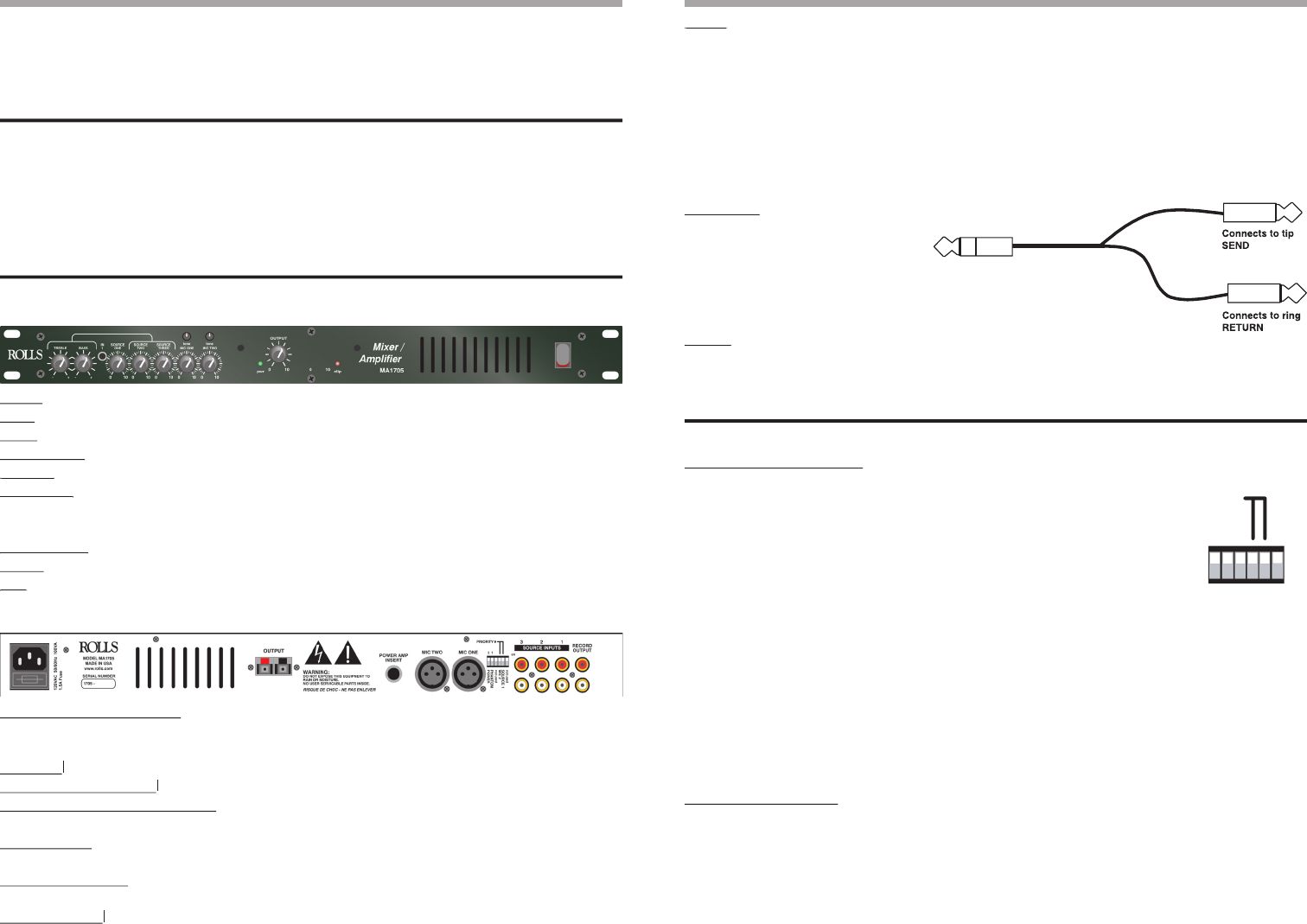
Amp Insert
Amp Insert
To connect a signal processor to the
MA1705 signal, use an insert plug,
or cable wired as shown in Fig. 1.
This return signal is then sent to the
output level section of the amplifier.
Output
Output
Connect 70 Volt speakers to the Output of the MA1705 by pressing in each of the spring-
loaded terminals and inserting the proper wire into the proper terminal i.e.; + = red, - =
black.
To Amp Insert
OPERATION
DIP SWITCH SETTINGS
(From left to right)
• If a microphone requires phantom power, move the Mic channel’s
corresponding PHANTOM POWER switch to the up position. This ap-
plies 12 volts dc phantom power to the indicated microphone.
• Mic 2 Priority; when in the up position, all program material on Mic 1
and Sources 2 and 3 will be “ducked” or muted when a signal is pres-
ent at Mic 2. Source 1 is left un-muted.
This function is used for paging.
• Source 1 Priority: when in the up position, Source 2,and 3 will be
“ducked” or muted by the signals at Source 1.
This function is for jukebox priority. With a jukebox connected to Source input 1, and the
Talkover switch 2 on, the other Source input signals such as background music, will be
muted and only the jukebox will be heard.
FAULT PROTECTION
The fault protection in the MA1705 limits the current to the output stage. This mode is en-
tered whenever the output stage is called upon for too much power, it may also be fooled
by impedances lower than four ohms - which may cause the output stage to overheat and
be irreversably damaged.
BURN WARNING!
THE FRONT PANEL OF THE MA1705 IS THE HEAT DISTRIBUTION FOR THE OUT-
PUT STAGE. IF THE UNIT IS OPERATED AT HIGH VOLUMES, IT MAY GET HOT.
SOURCE 1
MIC 2
on
PHANTOM
POWER
PRIORITY ◗
2 1
not used
not used