


7
Panel Descriptions
THRU OUT Section
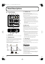
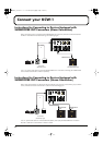
7. THRU OUT jacks
Signals input to the INPUT jacks are output here unchanged.
These are convenient when connecting to devices that have
no SUBWOOFER OUT. For detailed connection instructions,
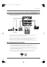
refer to “Instructions for Connecting to Devices With No
SUBWOOFER OUT” (p. 9).
Two types of connectors are provided: XLR connectors and
1/4” phone jacks. Use the type of connectors that match the
device you are connecting.
These output jacks provide +4 dBu line level output.
* No sounds are output from the THRU OUT jacks when the
power is turned off.
* The PHASE switch, BOTTOM switch, and CROSSOVER
knob do not affect the output from THRU OUT.
* When inputting only to the INPUT L (MONO) jack, the signal
is output from both the L and R jacks of THRU OUT.
8. GND LIFT switch
Allows you to make/break the connection between the GND
pins of the THRU OUT XLR connectors and the KCW-1’s
ground.
If you encounter noise problems that are possibly caused by
a ground loop, try changing the switch position to alleviate
the problem.
9. POWER switch
This switches the power on and off.
* Before turning the power on or off, be sure to put the VOLUME
knob at 0.
* This unit is equipped with a protection circuit. A brief interval
(a few seconds) after power up is required before the unit will
operate normally.
* Refer to p. 10 for the order in which to turn the power to
connected devices on and off.
* If you need to turn off the power completely, first turn off the
POWER switch, then unplug the power cord from the power
outlet. Refer to “Power Supply” (p. 5).
10. POWER indicator
This lights up when the power is on.
11. AC inlet
Connect the included Power cord here. Plug it firmly in, so
that the cable does not accidentally become disconnected.
■
Front Panel
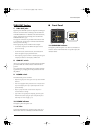
12. OPERATION indicator
This lights up when the power is on. When a connected foot
switch is used to switch off the KCW-1’s speaker output, the
indicator flashes.
12
KCW-1_e.book 7ページ 2006年9月8日 金曜日 午前11時50分