


4
1234567
8910
DESIGN FEATURES
INSTALLATION
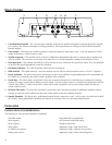
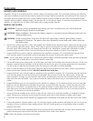
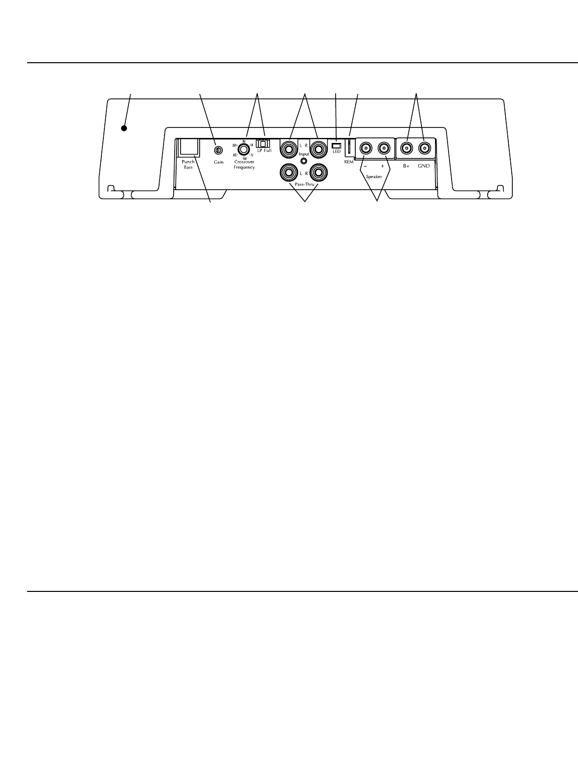
1. Cast Aluminum Heatsink – The cast aluminum heatsink of the Punch amplifier dissipates heat generated by the amplifi-
er's circuitry. The inherent advantage of casting provides a 30% improvement of cooling over conventional extrusion
heatsink designs.
2.
Gain Control – The input gain control is preset to match the output of most source units. It can be adjusted to match
output levels from a variety of source units.
3.
Variable Crossover – The amplifiers have a built-in 12dB/octave Butterworth filter with a crossover point variable from
50Hz to 250Hz. The crossover can be set to Low-Pass (LP) or it can be bypassed by setting it to Full Range (FULL).
4. RCA Input Jacks – The industry standard RCA jacks provide an easy connection for signal level input. They are gold-plat-
ed to resist the signal degradation caused by corrosion.
5.
LED Power Indicator – The LED illuminates when the unit is turned on.
6. REM Terminal – This spade terminal is used to remotely turn-on and turn-off the amplifier when +12V DC is applied.
7. Power Terminals – The power and ground connectors on the Punch amplifier are gold-plated and will accommodate up
to 8 AWG wire maximizing the input current capability of the amplifier.
8.
Punch Bass – The Punch Bass control helps correct for acoustical deficiencies in the listening environment by helping
produce full range sound without adding excessive boost.. The Punch Bass control is a narrow band adjustment at 45Hz
variable from 0dB to + 18dB. Connection is made with a cable using RJ-45 and can be installed under the dash for
remote control access.
9.
RCA Pass-Thru Jacks – The Pass-Thru provides a convenient source for daisy-chaining an additional amplifier without
running an extra set of RCA cables from the front of the vehicle to the rear amplifier location.
10.
Speaker Terminals – The heavy duty, gold-plated terminal block connectors (+ and –) will accept wire sizes from 8 AWG
to 18 AWG. These gold-plated connectors are immune to corrosion that can cause signal deterioration.
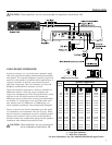
INSTALLATION CONSIDERATIONS
The following is a list of tools needed for installation:
Volt/Ohm Meter
Wire strippers
Wire crimpers
Wire cutters
#2 Phillips screwdriver
Battery post wrench
Hand held drill w/assorted bits
1/8" diameter heatshrink tubing
Assorted connectors
Adequate Length—Red Power Wire
Adequate Length—Remote Turn-on Wire
Adequate Length—Black Grounding Wire