


1
2
345678
10 1011 1312
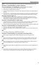
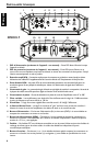
R500-1
9
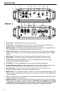
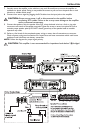
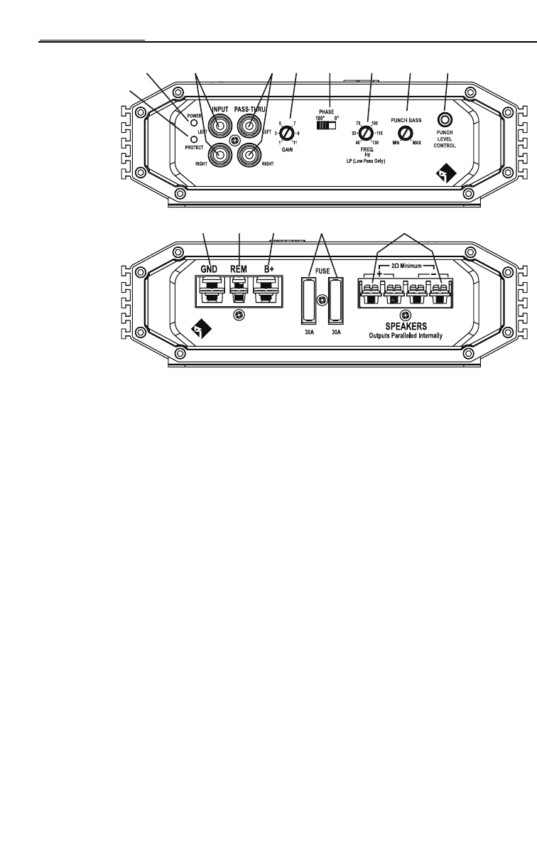
1. Power LED – This LED illuminates when the unit is turned on.
2. Protect LED – This LED illuminates if a short circuit or to low of an impedance is detected at the
speaker connections.The amplifier will automatically shut down if this occurs.
3. RCA Input Jacks – The industry standard RCA jacks provide an easy connection for signal level input.
They are nickel-plated to resist the signal degradation caused by corrosion.
4. RCA Pass-Thru Jacks – This Pass-Thru provides a convenient source for daisy-chaining an additional
amplifier without running an extra set of RCA cables from the front of the vehicle to the rear amplifier
location.
5. Gain Control – The input gain control is preset to match the output of most source units.
6. Phase Switch – Allows you to select the output phase of the amplifier between 0° and 180°.
7. Variable Crossover (Low Pass Only) – Is a built-in 12dB/octave Butterworth filter with a
crossover point variable from 40Hz to 130Hz.
8. Punch Bass – This is an adjustable Bass level control centered at 45Hz @ 12dB/octave.
9. Remote Punch Level Control – When connected, the “Gain Control” is linked and allows you to
remotely control the output level of the amplifier from the dash or center console.
10. Power Te rminals – The power and ground are nickel-plated clamp wire connectors and will
accommodate 4 AWG #8 (up to 1/2”) spade or ring style connectors.
11. REM Terminal – The nickel-plated clamp wire connector and will accommodate 8 AWG #8 (up to 3/8”)
spade or ring style connectors.This terminal is used to remotely turn-on and turn-off the amplifier when
+12V DC is applied.
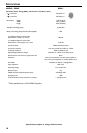
12. Fuses – These ATC fuses are easily accessible in case of failure.Always replace fuses with same type and
rating. See Specifications for fuse ratings.
13. Speaker Te rminals – The heavy duty, nickel-plated clamp wire connectors (
+
and -) will accommodate
8 AWG #8 (up to 3/8”) spade or ring style connectors. Two Positive (+) a
nd Negative (–) terminals
are provided for installation flexibility. Both terminals are wired in parallel internally. Only
one Positive (+) and one Negative (–) terminal is required for a speaker connection.
4
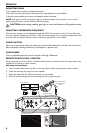
DESIGN FEATURES