


6
INSTALLA
TION
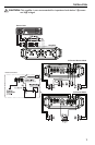
WIRING THE SYSTEM
CAUTION:If you do not feel comfortable with wiring your new unit,please see your
local Authorized Rockford Fosgate Dealer for installation.
CAUTION:Before installation,disconnect the battery negative (-) terminal to prevent
damage to the unit, fire and/or possible injury.
CAUTION:Avoid running power wires near the low level input cables,antenna, power
leads, sensitive equipment or harnesses.The power wires carry substantial
current and could induce noise into the audio system.
1. Plan the wire routing.Keep RCA cables close together but isolated from the amplifier's power cables
and any high power auto accessories,especially electric motors.This is done to prevent coupling the
noise from radiated electrical fields into the audio signal.When feeding the wires through the firewall
or any metal barrier,protect them with plastic or rubber grommets to prevent short circuits.Leave
the wires long at this point to adjust for a precise fit at a later time.
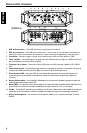
2. Prepare the RED wire (power cable) for attachment to the amplifier by stripping 3/8" of insulation
from the end of the wire.Crimp the bared wire into a fork or ring style connector and attach to the
B+ terminal.Tighten the screw to secure the cable in place.
NOTE:The B+ cable MUST be fused 18" or less from the vehicle's battery.Install the fuseholder under
the hood and ensure connections are water tight.
3. Trim the RED wire (power cable) within 18" of the battery and splice in a inline fuse holder (not
supplied).See Specifications for the rating of the fuse to be used. DO NOT install the fuse at
this time.
4. Strip 1/2" from the battery end of the power cable and crimp an appropriate size ring terminal to the
cable. Use the ring terminal to connect to the battery positive terminal.
5. Prepare the BLACK wire (Ground cable) for attachment to the amplifier by stripping 3/8" of
insulation from the end of the wire.Crimp the bared wire into a fork or ring style connector and
attach to the GROUND terminal.Tighten the screw to secure the cable in place.Prepare the chassis
ground by scraping any paint from the metal surface and thoroughly clean the area of all dirt and
grease.Strip the other end of the wire and attach a ring connector.Fasten the cable to the chassis
using a non-anodized screw and a star washer.
NOTE:Keep the length of the BLACK wire (Ground) as short as possible.Always less than 30"(76.2cm).
6. Prepare the Remote turn-on wire for attachment to the amplifier by stripping 3/8" of insulation from
the end of the wire.Crimp the bared wire into a fork or ring style connector and attach to the
REMOTE terminal.Tighten the screw to secure the wire in place.Connect the other end of the
Remote wire to a switched 12 volt positive source.The switched voltage is usually taken from the
source unit's remote amp on lead.If the source unit does not have this output available, the
recommended solution is to wire a mechanical switch in line with a 12 volt source to activate the
amplifier.
7. Securely mount the amplifier to the vehicle or amp rack.Be careful not to mount the amplifier on
cardboard or plastic panels.Doing so may enable the screws to pull out from the panel due to road
vibration or sudden vehicle stops.
8. Connect from source signal by plugging the RCA cables into the input jacks at the amplifier.
CAUTION:Always ensure power is off or disconnected at the amplifier before
connecting RCA cables. Failure to do so may cause damage to the amplifier
and/or connected components.
9. Connect the speakers.Strip the speaker wires 3/8",crimp the bared wire into a fork or ring style
connectors and attach to the speaker terminals.Tighten the screw to secure into place.Be sure to
maintain proper speaker polarity. DO NOT chassis ground any of the speaker leads as unstable
operation may result.
10. Perform a final check of the completed system wiring to ensure that all connections are accurate.
Check all power and ground connections for frayed wires and loose connections which could cause
problems.Install inline fuse near battery connection.
NOTE:Follow the diagrams for proper signal polarity.