


9
3. Strip 3/8" from the battery end of the power cable and crimp a large ring
terminal to the cable. Use the ring terminal to connect to the battery pos-
itive terminal. Do not install the fuse at this time.
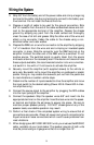
4. Prepare a length of cable to be used for the ground connection. Strip
5/8" of insulation from the end of the cable as described above and con-
nect to the appropriate terminal of the amplifier. Prepare the chassis
ground by scraping any paint from the metal surface and thoroughly
clean the area of all dirt and grease. Strip the other end of the wire and
attach a ring connector. Fasten the cable to the chassis using a non-
anodized screw and a star washer.
5. Prepare the REM turn-on wire for connection to the amplifier by stripping
1/4" of insulation from the wire end and crimping an insulated spade
connector in place. Slide the connector over the REM terminal on the
amplifier. Connect the other end of the REM wire to a switched 12 volt
positive source. The switched signal is usually taken from the source
units auto antenna or the accessory lead. If the source unit does not have
these outputs available, the recommended solution is to wire a mechan-
ical switch in line with a 12 volt source to activate the amplifier.
6. Securely mount the amplifier (with supplied screws) to the vehicle or
amp rack. Be careful not to mount the amplifier on cardboard or plastic
panels. Doing so may enable the screws to pull out from the panel due
to road vibrations or sudden vehicle stops.
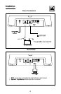
7. Determine the number of inputs needed to drive the amplifier and move
the input switch to the desired setting (Power 400 & Power 800 4-chan-
nel amplifiers only.).
8. Connect the source signal to the amplifier by plugging the RCA cables
into the input jack(s) at the amplifier.
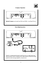
9. Connect the speakers. Strip the speaker wires 5/8" and insert into the
appropriate terminal on the amplifier. Insert the bare wire into the speak-
er terminal and tighten the set screw to secure into place. Be sure to
maintain proper speaker polarity. DO NOT chassis ground any of the
speaker leads, as unstable operation may result.
10. Perform a final check of the completed system wiring to ensure that all
connections are accurate. Check all power and ground connections for
frayed wires and loose connections which could cause problems from
road vibrations.
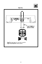
11. When bridging two BD110001/BD15001 units you must use the BDSYNC
cable, available at your local dealer. The speaker grounds of both units
must be joined using an 8 gauge wire that is no longer than 15”.
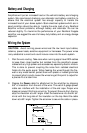
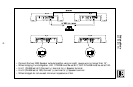
Wiring the System