


– 10 –
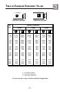
Punch 55.2, 75.2, 125.2
Trim the power cable to within 18" of the battery and install the protective
rubber boot, which is packed with the fuseholder, over the end of the wire.
Strip 3/8" of insulation from the wire and insert into the end of the
fuseholder, then crimp it in place. Slide the rubber boot into place to cover
the connection. Use the section of cable that was trimmed earlier and
connect it to the other end of the fuseholder.
Punch 225.2
Mount the fuseholder within 18" of the battery using two (2) #8 screws.
Disassemble the fuseholder. You should have 2 black plastic end caps,
2 gold-plated fuse clips, a plastic spacer and the fuseholder body. Trim
the amplifier power cable to reach the fuseholder and strip the wire 3/8".
Slide one of the end caps over the wire (narrow end first) and insert the
wire into one of the fuse clips. Tighten the set screw. Screw the black end
cap to the fuseholder body to secure the cable. Use the section of cable
that was trimmed earlier and connect it to the other end of the fuseholder.
Install the plastic spacer in the fuseholder and attach the cable to the
fuseholder body.
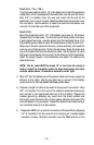
NOTE: The B+ cable MUST be fused 18" or less from the vehicle's
battery. Install the fuseholder under the hood and prepare the cable
ends as stated above. Connections should be water tight.
4. Strip 3/8" from the battery end of the power cable and crimp a large ring
terminal to the cable. Use the ring terminal to connect to the battery
positive terminal. Do not install the fuse at this time.
5. Prepare a length of cable to be used for the ground connection. Strip
5/8" of insulation from the end of the cable as described previously
and connect to the appropriate terminal of the amplifier. Prepare the
chassis ground by scraping any paint from the metal surface and
thoroughly clean the area of all dirt and grease. Strip the other end of the
wire and attach a ring connector. Fasten the cable to the chassis using a
non-anodized screw and a star washer.
6. Prepare the REM turn-on wire for connection to the amplifier by stripping
1/4" of insulation from the wire end and crimping an insulated spade
connector in place. Slide the connector over the REM terminal on the