


HSG2005
Rev.4.00 Jun 21, 2006 page 2 of 12
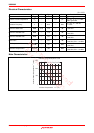
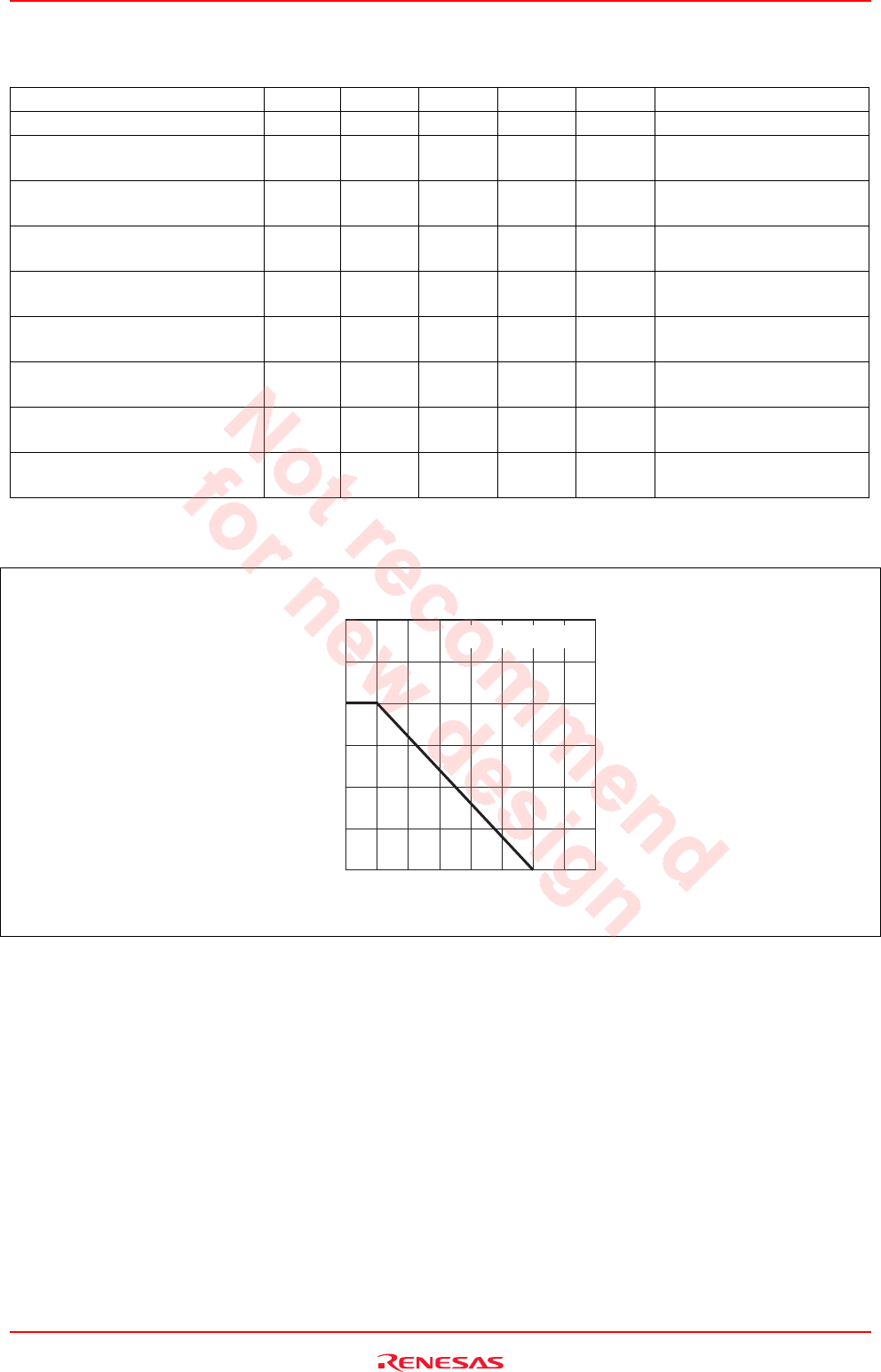
Electrical Characteristics
(Ta = 25°C)
Item Symbol Min Typ Max Unit Test Conditions
DC current transfer ratio h
FE
150 220 300 V
CE
= 3 V, I
C
= 100 mA
Reverse Transfer Capacitance C
re
0.4 pF
V
CB
= 3 V, I
E
= 0, f = 1 MHz,
emitter grounded
Transition Frequency f
T
28.5 GHz
V
CE
= 3 V, I
C
= 100 mA,
f = 1 GHz
Maximum Stable Gain MSG 10.5 12.5 dB
V
CE
= 3 V, I
C
= 100 mA,
f = 5.8 GHz
Maximum Available Gain MAG 17.0 dB
V
CE
= 3 V, I
C
= 100 mA,
f = 2.4 GHz
Maximum Available Gain MAG 9.0 dB
V
CE
= 3 V, I
C
= 100 mA,
f = 5.8 GHz
Power Gain PG 8.0 dB
V
CE
= 3.6 V, I
idle
= 100 mA,
f = 5.8 GHz, Pin = +13 dBm
1dB Compression Point at output
P1dB +21 dBm
V
CE
= 3.6 V, I
idle
= 100 mA,
f = 5.8 GHz
Saturation Output Power Po(sat) +23 dBm
V
CE
= 3.6 V, I
idle
= 100 mA,
f = 5.8 GHz, Pin = +13 dBm
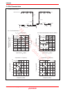
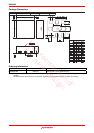
Main Characteristics
0 50 100 150 20
0
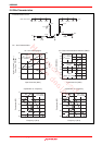
Collector Power Dissipation Pc
*
(mW)
Collector Power Dissipation Curve
Ambient Temperature Ta (°C)
1800
1200
600
*(4 x 4 x 1mm) on PCB