


QAMP-40 • 12
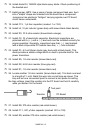
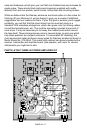
47. Locate the smaller transformer (T2) and install it snugly on the PC board.
48. Install the larger transformer (T1) into the indicated location on the PC
board.
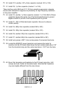
49. Install L1, a 19 turn toroid inductor wound previously. If desired, a small
dab of hot melt glue, bathtub sealer, or caulk may be used to secure the
toroids.
50. Install L2, the 22 turn toroid inductor - you marked it, remember?
51. Install L3, the remaining 19 turn toroid inductor.
This completes the assembly of your QRP power amplifier. Now's a good time to
give your masterpiece a good going over, being especially alert for any:
• bridged-over solder joints;
• misplaced components;
• transistors or diodes placed wrong;
• electrolytic capacitors installed wrong.
INITIAL TESTS:
To prepare your amplifier for testing you'll need the following:
• 1. Multimeter capable of measuring voltage and current.
• 2. 12 volt DC power source of at least 3 amp capacity.
• 3. Suitable dummy load and resonant antenna.
• 4. QRP transmitter with a power output in the ½ to 2 watt range,
such as the Ramsey QRP-40.
• 5. Proper cables to interface between the QRP transmitter and the
QRP power amplifier.
With the above all set up and handy, let's get testing!
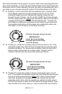
1. Rotate Bias pot R4 fully CCW.
2. Connect a multimeter to TP1 ; set the meter to read up to 5 volts DC.
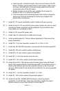
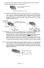
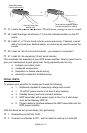
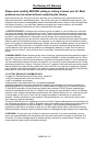
Secondary leads
(wound previously)
1 turn with loop then
another turn
Twist the loop together tightly
(not shown tightly for clarity)