


LPY2 • 8
parallel with the seam, the antenna will not function properly.
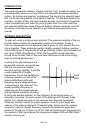
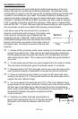
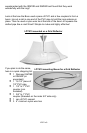
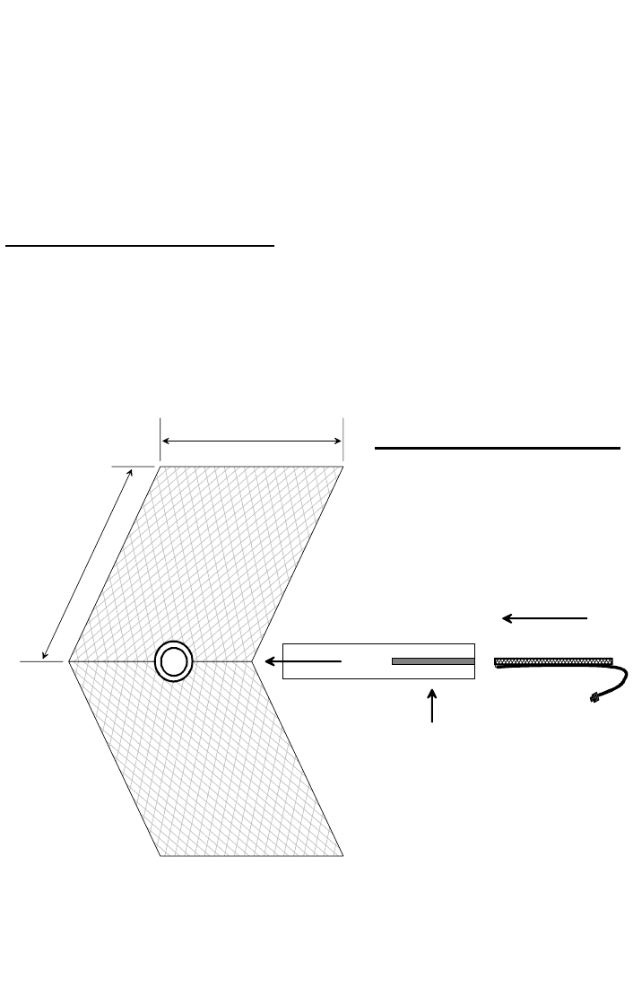
The boom length that positions the Logi at the focal point of the reflector is
also critical factor. This will require a bit of trial and error to get things just
right. Use a piece of PVC pipe (1/2” to 7/8” will work well) with a slot cut in the
end just big enough to wedge the entire Logi in place. The narrow front edge
of the circuit board should be positioned between 1.5” to 3” from the seam
formed by the two reflector plates. PVC couplers can be mounted in the vertex
of the reflector to allow you to slide the boom in and out while testing. Once
the optimal position of the Logi is set, tighten the coupler and your ready to go!
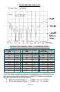
BUILDING A REFLECTOR GRID
Building a reflector grid antenna as a home-brew project is a little harder then
the corner reflector. It would be very difficult to achieve the proper parabolic
shape for the reflector by banging on an old BBQ grill! The best way to insure
your antenna will function the way you want is to use a pre-fabricated dish.
There are a few different dishes that are easy to get and very affordable. We
10.0" -12.0"
Cut a slot into
the PVC boom.
Insert the Logi
narrow end first.
90
°
Corner Reflector
Logi front edge placed
1.5" to 3" from vertex.
12.0"