


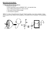

ASSEMBLY OF THE BN9
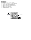
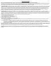
❒ 1. Orient the circuit board as shown in the Parts Layout Diagram.
❒ 2. Install U1, the LM-380 IC into the PC board, making sure that all 14 pins are in their proper
holes. Also note in which direction the notch is oriented in the Parts Layout Diagram. Make sure
U1 is mounted in the same way when you solder it in. To make soldering easier, flip the board
over so the pins are facing up. This way the part can be soldered flush to the board with ease.
Don’t worry about all the pins being tied together in the center, these are grounding pins that also
act as heat sinks to keep your amp from getting too hot during use.
❒ 3. Install Q1, the 2N3904 transistor. Notice the correct position of it’s flat side. Guide all three
leads into their respective holes and solder the part in place.
❒ 4. Install R1, a 220K ohm resistor (red-red-yellow).
❒ 5. Install R2, a 10K ohm resistor (brown-black-orange).
❒ 6. Install C1, a .01µF ceramic disk capacitor (marked 10nF, 103 or .01).
❒ 7. Install C2, another .01µF ceramic disk capacitor (marked 10nF, 103 or .01).