


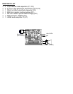


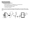

The following electrolytic capacitors are polarized and must be inserted with proper orientation to the
polarity markings. Usually the capacitors are marked with a side stripe to indicate the negative (-) pin
or rarely a plus symbol to indicate the plus side. NOTE: The Parts Layout Diagram designates the
holes where the positive (+) leads go.
❒ 8. Install C3, the 4.7µF or 10µF electrolytic capacitor.
❒ 9. Install C4, the 4.7µF or 10µF electrolytic capacitor.
❒ 10. Install C6, the 4.7µF or 10µF electrolytic capacitor.
❒ 11. Install C5, the 100µF or 500µF electrolytic capacitor.
Whew! what a challenge. It looks as if we are done installing all the components included with the kit
and we’re ready to toss this manual aside right? WRONG. We still need to go through some testing
procedures to make sure we have done everything correctly up to this point.
First of all check all of your solder joints and connections to make sure there are no solder bridges or
cold solder joints. Next check part orientations such as IC orientation and electrolytic capacitor
orientation. Now we are ready to begin testing.