12
WL115-sw Connections
Input Connections
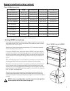
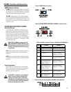
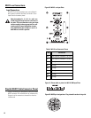
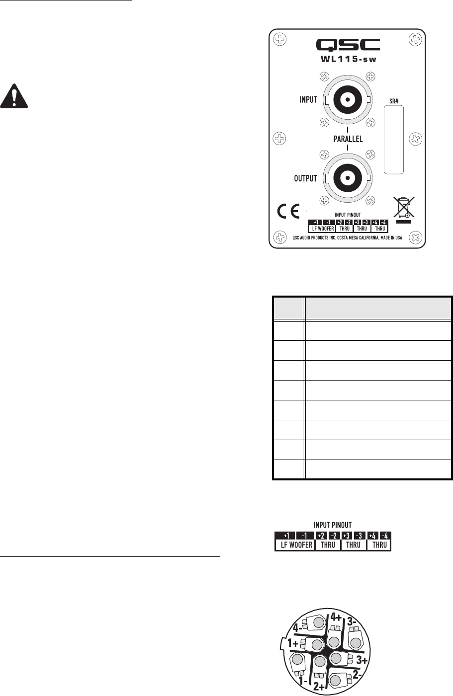
The WL115-sw input connectors are a pair of Neutrik
NL8's wired in parallel. See Table 3 or the WL115-sw
Input Plate for connector pinout.
Note pin numbers 2+, 2-, 3+, 3-, 4+, and 4- are
wired straight through from one connector to
the other. This accommodates using one input
cable assembly (where appropriate) for sub-
woofer and full range loudspeaker connec-
tions. Additionally, pin numbers 1+ and 1- of
both NL8s are wired in parallel.
Neutrik NL8FC Cable Connector Pinout
Figure 22 shows the pin designations inside the Neutrik
NL8FC connector. This information is for reference only.
Diagram is of the connector as viewed from the wire-
insertion end.
Figure22: NL8FC pin designations- Plug viewed from the wiring side.
Table 3: WL115-sw Connector Pinout
PIN Connection
1+
Low Frequency Transducer + (8 Ohms)
1-
Low Frequency Transducer - (8 Ohms)
2+
Through
2-
Through
3+
Through
3-
Through
4+
Through
4-
Through
Figure 20: WL115-sw Input Plate
Figure 21: Pinout table as printed on WL115-SW Input Plate


