


2
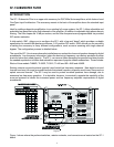
CONFIGURATION
SETTING THE SUBSONIC FILTER FREQUENCY
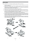
The subsonic (highpass) filter on Channel 1 cannot be bypassed, and Channel 2 should only be bypassed
in the bridged mono mode. Plug-in SIP resistor network RN3 sets the high-pass frequency for both channels
1 and 2. Table 2 shows the resistor value to be used for the frequency you desire. Typical subsonic
frequencies available with the provided SIP resistor networks are 20, 25, 32, 35, 40, 50, 63, and 80 Hz.
Consult your subwoofer manufacturer if you are unsure of what frequency to use.
If you desire a 6-dB boost at the low end of the subwoofer frequency range, set the slide switch SW1 to “ON”;
otherwise set it to “OFF.” Such a boost is popular with users of Electro-Voice B6 subwoofer enclosures.
SETTING THE SUBWOOFER UPPER FREQUENCY LIMIT
The low-pass filter sets the upper limit of the subwoofer frequency range. Plug-in SIP resistor network RN4
sets the low-pass frequency for both channels 1 and 2. Table 2 shows the resistor value to be used for the
frequency you desire. Typical frequencies available with the provided SIP resistor networks are 100, 135,
160, 200, and 250 Hz. Consult your subwoofer manufacturer if you are unsure of what frequency to use.
Whatever frequency you choose should be higher than that of the subsonic filter.
SETTING DIP SWITCH SW2
Determine the configuration you desire and set the DIP switches as described below.
Positions 1 through 4 and 9 and 10
First, decide whether you need “Mono Sum” or “Stereo” operation. This will determine the settings of
positions 1 through 4 and 9 and 10 of DIP switch SW2.
• Mono Sum
Because it is difficult for listeners to sense directionality of low audio frequencies, many subwoofer
systems are set up for monaural operation, with both channels summed together. For mono
summed operation, set the amplifier mode switch to “STEREO” and SW2 as follows:
Position 1 OFF
Position 2 ON
Position 3 ON
Position 4 OFF
Position 9 OFF
Position 10 ON
Continue to “Positions 5 through 8” and set those switches to engage both channels’ low-pass
filtering.
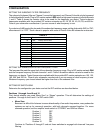
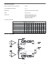
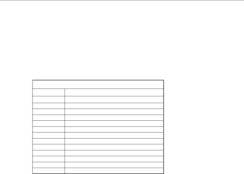
TABLE 2
Frequency Resistor Network Value (RN3 or RN4)
20 82K Factory set for RN3
25 68K
32 56K
35 47K
40 39K
50 33K
63 27K
80 20K
100 18K
135 12K
160 10K
200 8.2K
250 6.8K Factory set for RN4