


9
INPUT/OUTPUT
PIN
2+
1+
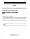
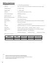
2430 LBS /3400 LBS / 1700 LBS / 771
WEIGHT 206 LBS
WORKING
WL218-sw
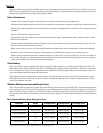
SUSPENSION OF THIS PRODUCT SHOULD BE
DONE BY QUALIFIED PERSONS FOLLOWING
SAFE RIGGING PRACTICES. OTHER RIGGING
LIMITATIONS MAYAPPLY. SEE WARNINGS IN THE
QSC AUDIO PRODUCTS, LLC
COSTA MESA CALIFORNIA, MADE IN USA
1+
1+
1-
2+
2-
2-
1-
2+
NL1
NL2
1+
1-
2-
2+
1+
1-
2-
2+
+
-
+
-
+
-
+
-
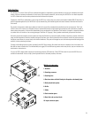
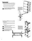
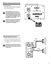
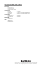
WL218-sw Controls and Connections
Input Connections
The WL218-sw input connectors are a pair of Neutrik
NL4's wired in parallel. See Table 2 or the WL218-sw
Input Plate for connector pinout.
Note pin numbers 2+ and 2- are wired
straight through from one connector to the
other. This accommodates using one input
cable assembly (where appropriate) for sub-
woofer and full range loudspeaker connec-
tions. Additionally, pin numbers 1+ and 1- of
both NL4s are wired in parallel.
The WL218-sw loudspeaker is not equipped
with a crossover network. All signal pro-
cessing must be done before connecting
audio power to the loudspeaker.
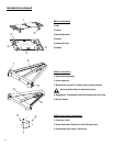
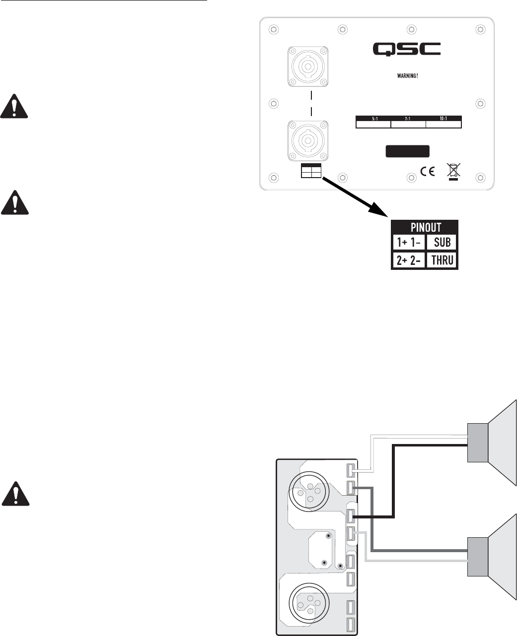
Reconfiguring the Input Connections for
Separate Transducer Connection
If separate transducer connection is required, the input
plate may be removed and the wiring altered so that
each transducer has a separate, dedicated connection.
Or, the transducers can be connected in parallel on pins
1+, 1- or pins 2+, 2-.
If alterations to the wiring are made, ensure
the input panel and connectors are clearly
marked so the next user is aware of the mod-
ification made.
WL218-sw Input Plate and pinout detail
White
Grey
Orange
Black