


QSC Audio Inc. 1675 MacArthur Boulevard • Costa Mesa, CA 92626 • Ph: 800/854-4079 or 714/957-7100 • Fax: 714/754-6174 • www.qscaudio.com
SF-3 SPECIFICATIONS
GENERAL INFORMATION
Subsonic filter frequency
Subsonic fitler Q
Output to amplifier
Accessory’s operating power
GENERAL AUDIO
Input stage type
Male HD-15 connector to amplifier DataPort
Male HD-15 connector to amplifier DataPort
Electronically balanced differential; both inputs summed
Output stage type Balanced
Dynamic range 118 dB nominal
Total harmonic distortion Less than 0.1%
Signal to noise ratio Min. 103 dB
Subsonic filter type 2nd-order, 12 dB/octave
Low-pass filter type
Low-pass roll-off slope
4th-order Linkwitz-Riley alignment; -6 dB at crossover frequency
24 dB/octave rolloff
SF
-3
Supply Voltage (no load)
+15 volts provided by amplifier, -15 volts provided by internal charge-pump converter.
Supply Current Requirements
Less than 50 mA
Operating Temperature
0–70
o
C
Input type, each channel
Electronically balanced differential
Input impedance
22.6 k‰balanced; 11.3 kΩ unbalanced
CONTROLS (each channel)
Selectable using SIP resistor networks: 20, 25, 30, 35, 40 & 50 Hz
Selectable using DIP switch: 0.707 (Butterworkth) or 2 (6 dB peak)
Low-pass filter
Bypass or engage using DIP switch
Low-pass filter frequency
Gain adjustment
Selectable using SIP resistor networks: 80, 150 & 250 Hz
Trim potentiometer 0–20 dB attenuation
CONNECTORS
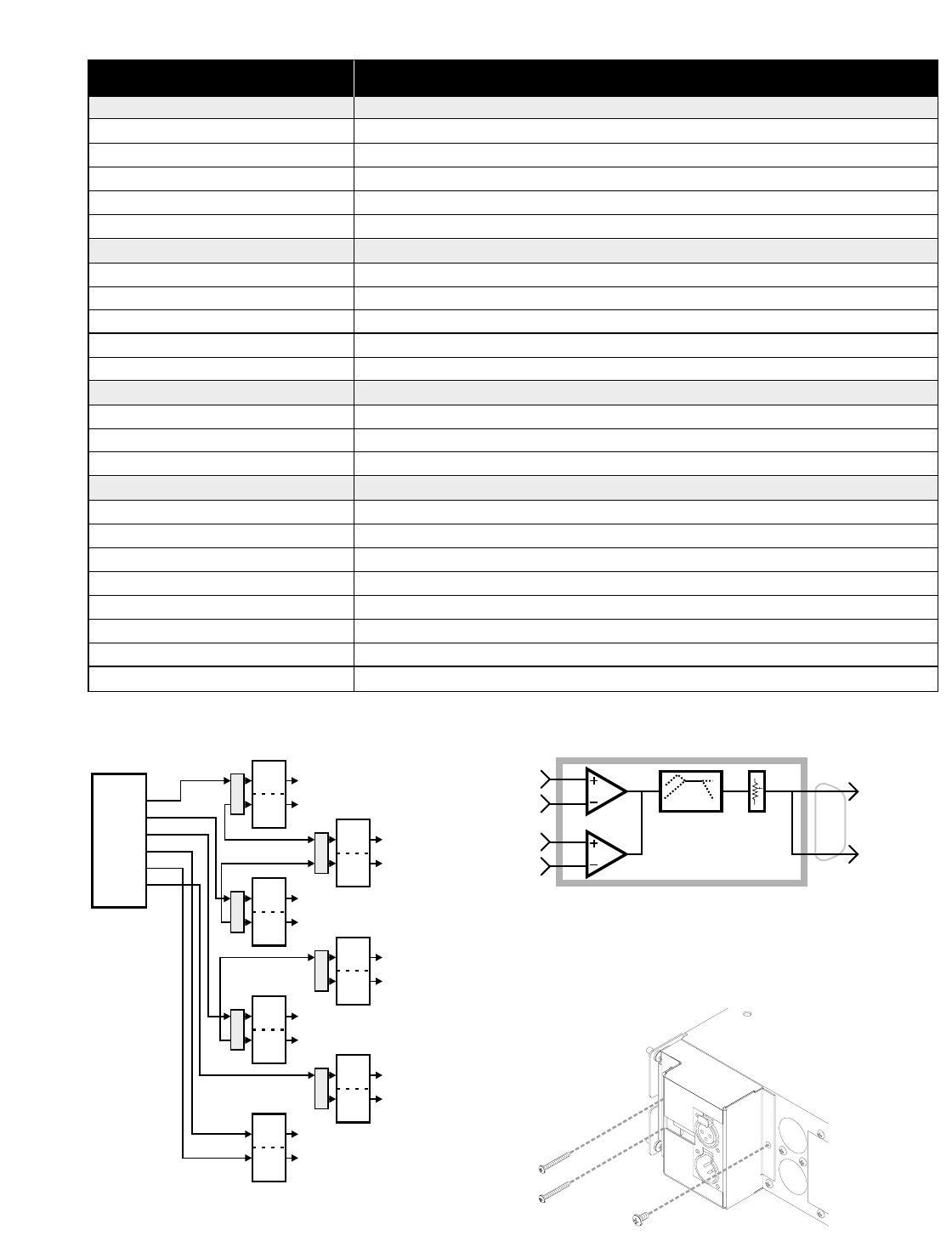
Input
Two female 3-pin XLR
1
1
1
2
2
2
LF-3LF-3SF-3
1
1
1
1
2
2
2
2
XC-3XC-3XC-3
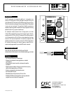
L
C
R
LS
RS
Sub
5.1
Cinema
Processor
DCA
DCA
DCA
DCA
Left
MF
Center
MF
Right
MF
Left
Surround
Left
HF
Center
HF
Right
HF
Right
Surround
DCA
DCA
DCA
Left
LF
Right
LF
Sub
Center
LF
Sub
Spare
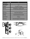
DataPort
Audio* in
Channel 1
Audio* in
Channel 2
SF out
Channel 1
SF out
Channel 2
Level trim
0…-20 dB
SF filtering
*Either full-range (for derived subwoofer program)
or discrete subwoofer program