


Connections
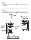
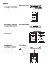
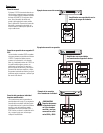
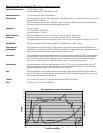
Normal Connection
The LF-3215 has barrier strip screw termi-
nals for connection. The terminals accept
up to #10 AWG (5.3mm
2
) stranded loud-
speaker wiring. Use the largest wire size
and shortest wire length possible for the
application. Observe the polarity markings
and keep polarity consistent throughout
the system for best performance.
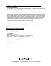
Parallel Connection of Second LF-3215
The terminals marker SPK2 may be used to
connect another LF-3215 in parallel. Con-
nect the wires as shown in the illustration,
at right. Note: If the LF-3215’s internal wir-
ing has been modified in any way, this may
not function. If this is the case, remove the
terminal cup and verify the presence of the
factory yellow jumper and blue jumper
wires; remedy as required or have the
loudspeaker serviced.
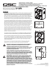
Individual Transducer Connection
(requires modification)
The transducers are wired in parallel
inside the enclosure. If individual trans-
ducer connection is required, remove the
terminal cup and remove the yellow and
the blue jumper wires that are connected
between the SPK1 and SPK2 terminals.
Replace the terminal cup and mark the
enclosure with a note of the modification.
Normal Connection Example:
Parallel Connection Example:
Individual Transducer
Connection Example:
Amplifier capable of
driving 4 ohm loads
Amplifier capable of
driving 2 ohm loads
CAUTION! Requires
removal of terminal
cup and removing
both the yellow and
the blue jumper
wires that connect
the SPK1 and SPK2
terminals.