


2 PLC0012 rev. A.
Contact information
This bulletin is available for download from the Service Bulletins page in the
Tech Support
section of the QSC Audio Web site:
http://www.qscaudio.com/support/technical_support/bulletins.htm. If you need any further information regarding this
service procedure, please contact QSC Technical Services at the addresses or numbers below.
Telephone:
1-800-772-2834 (within USA only)
+1 (714) 957-7150
Fax:
+1 (714) 754-6173
E-mail:
tech_support@qscaudio.com
Web sites:
www.qscaudio.com (product info/support)
www.qscstore.com (on-line accessory and replacement component sales)
Postal and parcel address:
QSC Audio Products, LLC
Technical Services Group
1665 MacArthur Blvd.
Costa Mesa, CA 92626 USA
Installing the new faceplate
10. Put the new faceplate in place and install all six mounting screws. Note
that the faceplate’s side panel mounting holes are not threaded. The self-
tapping mounting screws for these holes are meant to cut threads in the
cast aluminum, so they may be difficult to tighten; when tightening a
self-tapping screw, you might sometimes need to loosen it slightly before
tightening further.
11. Peel the backing from the label with the amp model number (6) and
carefully place it on the left side of the faceplate. Press it firmly in place.
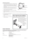
12. Pass the switch wires through the faceplate opening for the power
switch (5). Attach them to the switch (Figure 2).
13. Orient the switch as shown in Figure 2 and press it into the faceplate
opening. It will snap into place.
14. Reinstall the gain/display board. Place the lockwashers and nuts and tighten them snugly, but be careful not to overtighten
them.
15. Peel the backing from the LED lens label (4) and carefully place it on the right side of the faceplate. Press it firmly in place.
16. Place the gain label (3) on top of the LED
lens label. Press it firmly.
17. Press the knobs (2) onto the gain control
shafts.
18. Reinstall the bottom cover (1) and make sure
the amp works properly.
CARLINGSWITCH
15A 250VAC
20A 125VAC
723R
Red
Black
wire
wire
This end
toward top
of amplifier
Rear support for power amplifiers
Especially in a mobile or portable sound system, a power amplifier
mounted in an equipment rack should also be supported at the rear to
prevent damage, such as bending or cracking, to the faceplate.
The QSC Technical Services Group offers rear
rack ear kits for securing an amplifier to the
rack’s real rails. They are available in two
lengths, 3 and 7 inches (75 mm and 177 mm).
Each kit includes two L-bracket ears and the
necessary screws and hardware.
The QSC part number for the
shorter rear rack ear kit is
FG-000031-00. The
part number for the
longer kit is
FG-000081-00.
Figure 2. Wiring and orientation of the power
switch.