


23
OPERATION
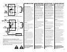
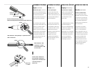
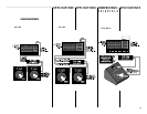
AC power switch
Before applying power, check all
connections and turn down the gain
controls. The "soft start" sequence
starts with the
POWER
indicator
LED at half brightness. A few
seconds later the fan starts, the
POWER
indicator fully illuminates
and the amplifier mutes for two
seconds. The
CLIP
LEDs will glow
bright red. When the CLIP LEDs go
out, the amplifier is ready for
operation.
UTILISATION BETRIEBOPERACIÓ N
Interrupteur
d'alimentation CA
Avant de mettre l'amplificateur en
marche, vérifiez toutes les connexions
et fermez les contrôles de gain. A la
mise en marche, la fonction "Soft
start" est activée, avec comme indication
l'allumage de la DEL
POWER
à demi-
intensité. Quelques secondes plus tard
le ventilateur démarre et l'amplificateur
passe en mode protection pour une
seconde, tel qu'indiqué par la DEL
CLIP
qui passe au rouge. La DEL
POWER
passe alors à pleine intensité et
l'amplificateur est prêt à fonctionner.
Netzschalter
Bevor Sie einschalten, überprüfen
Sie alle Verbindungen und drehen
Sie die Verstärkung zurück. Die
Softstart-Sequenz beginnt mit
halber Helligkeit der
POWER
LED.
Einige Sekunden später beginnt der
Ventilator zu laufen und der
Verstärker schaltet für etwa eine
Sekunde stumm, wobei die rote
CLIP
LED hell aufleuchtet. Danach
erscheint die
POWER
-Anzeige in
voller Helligkeit und der Verstärker
ist betriebsbereit.
Interruptor de encendio
Antes de encender el equipo, revise
las conexiones y baje los controles
de ganancia. La secuencia de
encendido "suave" inicia con el
indicador LED
POWER
a media luz.
Un par de segundos después el
ventilador se enciende y el
amplificador hace un silencio
momentáneo de protección, que se
puede visualizar en los indicadores
LED rojos de
CLIP
. Después el
indicador
POWER
se enciende
completamente y el amplificador
está listo para operar.
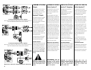
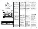
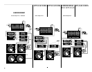
LED indicators
At full brightness, the green
POWER
LED indicates that the
amplifier is operating. Half
brightness means the amp is in its
startup sequence or that the
amplifier is in
STANDBY
mode.
As the input signal strength
increases, the green
SIGNAL,
-20dB,
and amber
-10dB
LED
indicators light respectively at 0.1%,
1% and 10% of full power.
The red
CLIP
LED indicator flashes
during overload (clipping). A bright,
steady glow indicates protective
muting. If this occurs during use, see
Troubleshooting.
The yellow
BRIDGE
LED illuminates
when the amp is in bridged mono
mode.
The orange
PARALLEL
LED
illuminates when the amp is in
Parallel Input mode.
Indicateurs DEL
Au fur et à mesure que le niveau de
signal augmente, les DEL vertes
SIGNAL
,
-20dB
, et
-10dB
allument
respectivement à 0.1%, 1%, et 10% de
la pleine puissance de l'amplificateur.
La DEL
CLIP
clignote lors de surcharges
(écrêtement). La DEL reste allumée à
pleine intensité pour indiquer la mise
en sourdine par le circuit de
protection. Si cette condition se
présentait lors de l'utilisation, voir la
section dépannage de ce manuel.
La DEL jaune
BRIDGE
indique que
l'amplificateur a été réglé en mode
ponté mono.
La DEL jaune
PARALLEL
indique
que l'amplificateur a été réglé en
mode parallèle.
Indicadores LED
A medida de que la señal aumenta,
los indicadores verdes de
SIGNAL
,
los de
-20 dB
y
-10 dB
, se iluminan
respectivamente al 0.1%, 1%, y 10%
de la potencia máxima.
El indicador LED rojo de
CLIP
,
parpadea cuando hay saturación
(clips). Cuando permanece
encendido indica "enmudecimiento"
(función Mute) de protección. Si
ocurre durante el uso, lea la sección
Solución de Problemas.
El LED amarillo de
BRIDGE
indica
que el amplificador está en modo
puenteado en mono.
El LED amarillo de
PARALLEL
indica
que los interruptores de entrada
paralela se han activado.
LED-Anzeige
Bei steigendem Eingangssignal,
leuchten die grünen
SIGNAL
,
-20dB
und
-10dB
LEDs nacheinander auf
und zeigen 0,1%, 1% und 10% der
möglichen vollen Leistung an.
Die rote
CLIP
LED leuchtet während
Übersteuerungen (Clipping) auf. Ein
helles, gleichmäßiges Leuchten zeigt
außerdem schützendes Stummschalten
an. Falls dieser Zustand während des
Betriebs auftritt, lesen Sie bitte den
Abschnitt Fehlerbehebung.
Die gelbe
BRIDGE
LED leuchtet auf,
wenn der Verstärker Monobrücke
betrieben wird.
Die gelbe
PARALLEL
LED zeigt an,
daß die Parallel Input Schalter
eingestellt wurden.
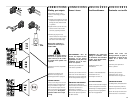
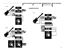
Gain controls
The gain controls are detented (21
steps) for repeatable adjustment.
Surrounding the gain control knob,
the attenuation level is shown in dB.
Maximum gain differs by model and is
given in the table at the left.
Contrôles de gain
Les contrôles de gain à taquets
permet les réajustements répétés. Le
gain en tension de l'amplification est
indiqué en dB.
Verstärkungsregler
Die Regler wurden als Rastpotentio-
meter ausgelegt, um reproduzierbare
Einstellungen zu erlauben. Die
tatsächliche Verstärkung wird in dB
angezeigt.
Controles de ganancia
Los controles de ganancia han sido
diseñados para un ajuste continuo.
El voltaje de ganancia del amplificador
aparece en decibeles.
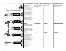
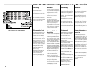
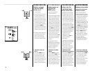
Front Panel (right side)- LED indicators and Gain controls
-ledoM 812LP 422LP 032LP 632LP
mumixaM
BdniniaG
Bd23Bd43Bd53Bd63
Maximum Gain (in dB) by Model Number
Power Switch Operation
LED indicators
Gain Control
Ch.1
Gain Control
Ch. 2
23