


10
Rigging the Installation Line Array (continued)
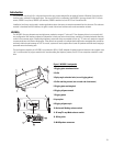
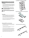
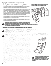
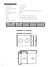
Attaching WL115-sw behind WL2082-i array using EB2082-i
It is sometimes necessary to suspend the subwoofers behind the main array. Extreme
splay angles may result in physical interference with rear-flown subwoofers.
Attach both array frames to the extension bar rigging plates by centering the array frame
member between the extension bar rigging plates and bolting together using the sup-
plied 7/8” bolts. The extension bar rigging plates can be moved, if required, by removing
the two 7/8”mounting bolts, moving to the selected mounting location, and reattaching.
Tightening torque is to be 100 lb-ft (135.6 N-m). Ease-Focus software’s center-of-gravity
calculator will provide a suitable point (or two points) for desired down-tilt.
The rear suspended WL115-sw subwoofer(s) may now be attached to the array frame;
see “Attaching the WL115-sw to the Array Frame”
The front suspended WL2082-i loudspeakers may now be attached to the array frame;
see “Attaching WL2082-i to Array Frame”
NOTE: When stacking loudspeakers for attachment to array frames using
the extension bar, we recommend working with groups of 2 WL2082-i for
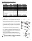
each WL115-sw. Start with no splay angle; this yields the same height for landing the extension
bar. Adjust splay angle once the rig is lifted.
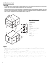
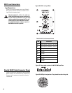
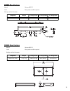
Suspending 4 or less WL2082-i Loudspeakers Using Two Pull-Back Bars
NOTE: Do not suspend more than 4 WL2082-i loudspeakers from a PB2082-i pull-back bar! Do not
use PB2082-i pull-back bar for suspending anything other than 4 or less
WL2082-i loudspeakers! Do not suspend the WL115-sw from the PB2082-i
pull-back bar!
NOTE: A washer should not be used when attaching the pull back bar. This
will allow the pull back bar to pivot freely.
Assemble the array of WL2082-i loudspeakers on the ground using the included mating
hardware. Ensure the notched rigging plate is on the right hand side (the system can only
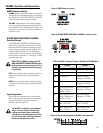
be installed one way. Note the QSC logo on the input plate will appear right side up when
the enclosure is oriented properly.
Attachment of one enclosure to another is accomplished by inserting the cap-head shoul-
der bolt with washer through the mated rigging plates and appropriate splay angle selec-
tion holes and threading the lock nut (nylock) on the inside edge of the plates. The bolt
should be tightened snuggly to no more than 5 lb-ft of torque (6.8 N-m). See Figure 7 for
assembly detail.
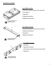
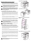
Attach one PB2082-i to the top enclosure’s front, top rigging plate attachment holes by
inserting the cap-head shoulder bolts without washers through the mated pieces and
threading the lock nut (nylock) on the inside edge of the plates. The bolts should be tight-
ened snuggly to no more than 5 lb-ft of torque. See Figure 7 for assembly detail. Use a 5/
8” (16 mm) screw pin anchor shackle to attach to the pull-back bar shackle hole located in
the center of the pull back bar for lifting.
Attach the second PB2082-i to the bottom enclosure at the bottom-most splay angle
adjustment holes at the rear of the rigging plate by inserting the cap-head shoulder bolts
without washers through the mated pieces and threading the lock nut (nylock) on the
inside edge of the plates. The bolts should be tightened snuggly to no more than 5 lb-ft
(6.8 N-m) of torque. See Figure 7 for assembly detail. Use a 5/8” (16 mm) screw pin anchor
shackle to attach to the pull-back bar shackle hole located in the center of the main bar for
pulling back.
Figure 16: Using two PB2082-i Pull Back Bars for
suspending a maximum of 4 WL2082-i loudspeakers.
Figure 15: EB2082-i with WL115-sw suspended at
rear and WL2082-i array suspended at front.
Warning! Four (4) WL2082-i loudspeakers
is the maximum allowable load (10:1
design factor) for the PB2082-i. Do not sus-
pend more than four WL2082-i loudspeakers from
the PB2082-i.