


11
EN
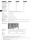
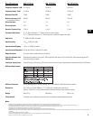
Specifications
MD-FP152/64r MD-FP152/94r MD-FP152/124r
Frequency Response, ±3dB 50-17.5k Hz 50-19k Hz 50-19k Hz
Frequency Range, -10dB 45-18k Hz 45-20k Hz 5-20.5k Hz
Maximum Peak SPL 129dB 129dB 129dB
Nominal coverage, H x V 60°x40° 90°x40° 120°x40°
(as installed at factory)
Directivity Index 12.8 11.3 9.6
Directivity Factor 19.0 13.4 9.1
Acoustic Crossover Freq. 1.32k Hz 1.4k Hz 1.2k Hz
Transducer Description LF: 15” (381mm) diameter, 4” (102mm) voice coil, ferrite magnet
HF: 1.4” (36mm) exit diameter, 2.5” (64mm) voice coil, neodymium magnet, all models
Amp Power LF: 800W, HF: 200W, all models
Input Sensitivity 1.2V
rms
(+4dB), all models
Input Headroom/Clipping 7.5V
rms
(+19.5dB), all models
Input Connector/Impedance XLR female, 20k ohm, balanced, all models
Output Connector XLR male, wired in parallel with Input connector
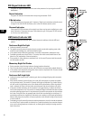
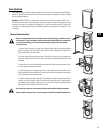
Controls, Indicators, and Rotatable horn assembly, Gain control, 100 Hz high-pass filter switch, Clip/Limit (red LED), Signal presence (green LED),
Adjustments Power (blue LED), all models
Protection, Agency certs. Thermal limiting, On/Off muting, AC in-rush current limiting, FCC class B (conducted and radiated emissions), UL/CE listed
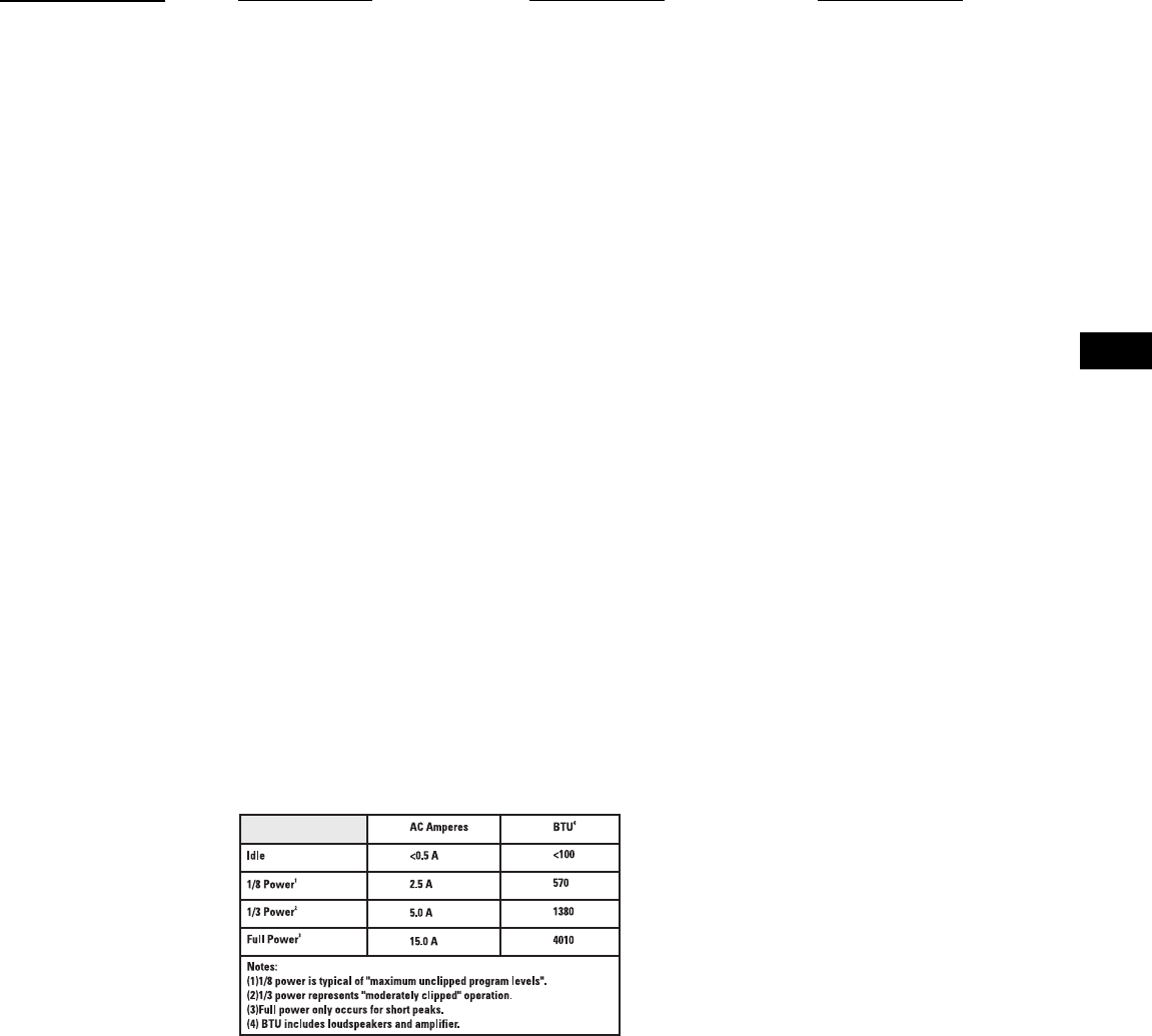
AC Power Requirements
AC Power Connector Factory supplied cordset: Neutrik Powercon on 10’ (3m) #18AWG 120V North American cordset
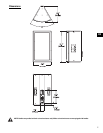
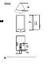
Dimensions 20.5” (521mm) W, 35.0” (889mm) H, 17.1” (432mm) D, including rear heatsink fins
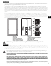
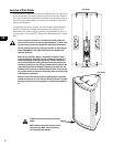
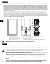
Allow for 100mm (4.0”) of free space behind the enclosure to assure proper amplifier cooling
Weight 89 lb/41 kg 88 lb/40 kg 89 lb/41 kg
Finish and Grill All models- wear resistant textured paint finish with powder-coated perforated steel grill
Notes:
1- Maximum Peak SPL: Calculated by adding the loudspeaker’s sensitivity (1W at 1m) to the peak power (dBw) of the amplifier provided.
2- Coverage: Included angle between -6dB points, plus X, minus Y dB, 500 to 3.2k Hz, taken at ISO preferred one-third octave intervals, or for an otherwise specified frequency range.
3- Directivity Index (DI): Difference between on-axis SPL and average SPL (considering all axes) for the specified coverage range. DI= 10 log Q
4- Directivity Factor (Q): Directivity index expressed as a power ratio Q=10 exp DI/10
5- Amplifier Power: The maximum sustained power at less than 1% clipping, averaged over the intended frequency range,
6- Input Sensitivity: The sine-wave input voltage required to reach amplifier clipping, measured within the frequency range used to determine Maximum Peak SPL, with the gain on “normal” and no gain reduction due
to limiting.
7- Input Headroom/Clipping: Maximum input voltage.
8- Input Connector/Impedance: RF shunt capacitance should not reduce impedance by more than 30% at 20k Hz.
9- TBD= to be determined, data not available at time of printing