


APPLICATIONS: GENERAL APPLICATION INFORMATION
The ISA 280, ISA 450 and ISA 750 amplifiers are optimized for directly driving low impedance loads. Low impedance (Lo-Z) loads are
those loads between 2 and 16 ohms. These models are not suitable for driving “constant voltage” 70V lines. These low impedance
models are referred to collectively as the “non-T” models. The Lo-Z outputs will handle impedances down to 2 ohms. 2 ohm loads
demand substantially higher output currents from the amplifier and should be approached with some caution. If operated at reasonable
power levels (similar to 1/8 rated power with pink noise test signal) with 2 ohm loads, the amplifier will perform exceptionally. At high
power with chest-pounding bass program material, excessive clipping with 2 ohm loads may cause excessive heat in the amplifier and
trigger thermal shutdown.
The ISA 300T, ISA 500T and ISA 800T amplifiers have the additional capability of driving constant voltage distributed audio lines of 25,
70 and 100 volts. The outputs are autotransformer coupled; they are not fully isolated. These autotransformer equipped models also
have low impedance outputs for added flexibility of system design and configuration. The total available output power from each
channel can be shared between the direct low impedance outputs and the autotransformer coupled high impedance outputs. These
high impedance capability models are referred to collectively as the “T” models.
General ISA Application Information-
Distributed Line Principles (“T” models only)
Distributed lines are the easiest and most reliable way of distributing audio to many low-power speaker loads located over a wide
area. It is easy to use because all the loads are connected in parallel across a pair of wires; there is normally no need to put speakers
in series or series-parallel arrangements to meet specific impedance requirements. It is reliable because the parallel connection
scheme makes it so that if any one speaker fails, the remaining speakers will continue to operate. Additionally, since the operating
voltage of distributed lines is fairly high, the current through the line is kept fairly small; this minimizes resistive losses in the wiring.
Distributed line systems are usually referred to by their nominal operating voltage with 25, 70 and 100 volt systems being the most
common. The main difference with the various operating voltages will be the “type” of matching transformer on the speaker assembly.
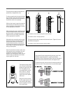
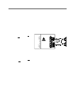
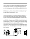
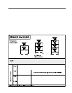
In the illustration below, the 70 volt transformer is connected to the 70 volt output terminals of channel 2 of the amplifier. The input to
the transformer may be connected to different “taps” that determine the nominal power that will be delivered to the speaker. The
example shows taps available for 2.5, 5, 10 and 20 watts with 10 watts selected. Some transformers have the capability of matching
the distributed line to several speaker impedances. If this is the case in your system, ensure that the speaker is connected to the tap
that matches its impedance. 70 volt systems are common in North America, while 100 volt systems are more common in Europe. 25
volt systems are typically older commercial intercom-type components being maintained with new amplifiers.
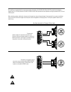
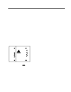
The example below shows a 70 volt line with one speaker load attached. Most distributed lines will have many speakers connected in
parallel across the line. To estimate the power handling requirements for a line, simply add up all the “speaker load powers”. Below,
the selected “speaker load power” is 10 watts. If there were 10 of theses exact same loads on the line, then the line would represent a
100 watt load to the amplifier’s 70 volt output terminals. The example would be the same if the system were 25 volt or 100 volt. Only
the matching transformer would be marked with the 25V or 100V rating and the connections to the amplifier would be at the appropri-
ate 25V or 100V output terminals.
27