


17
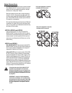
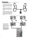
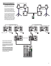
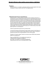
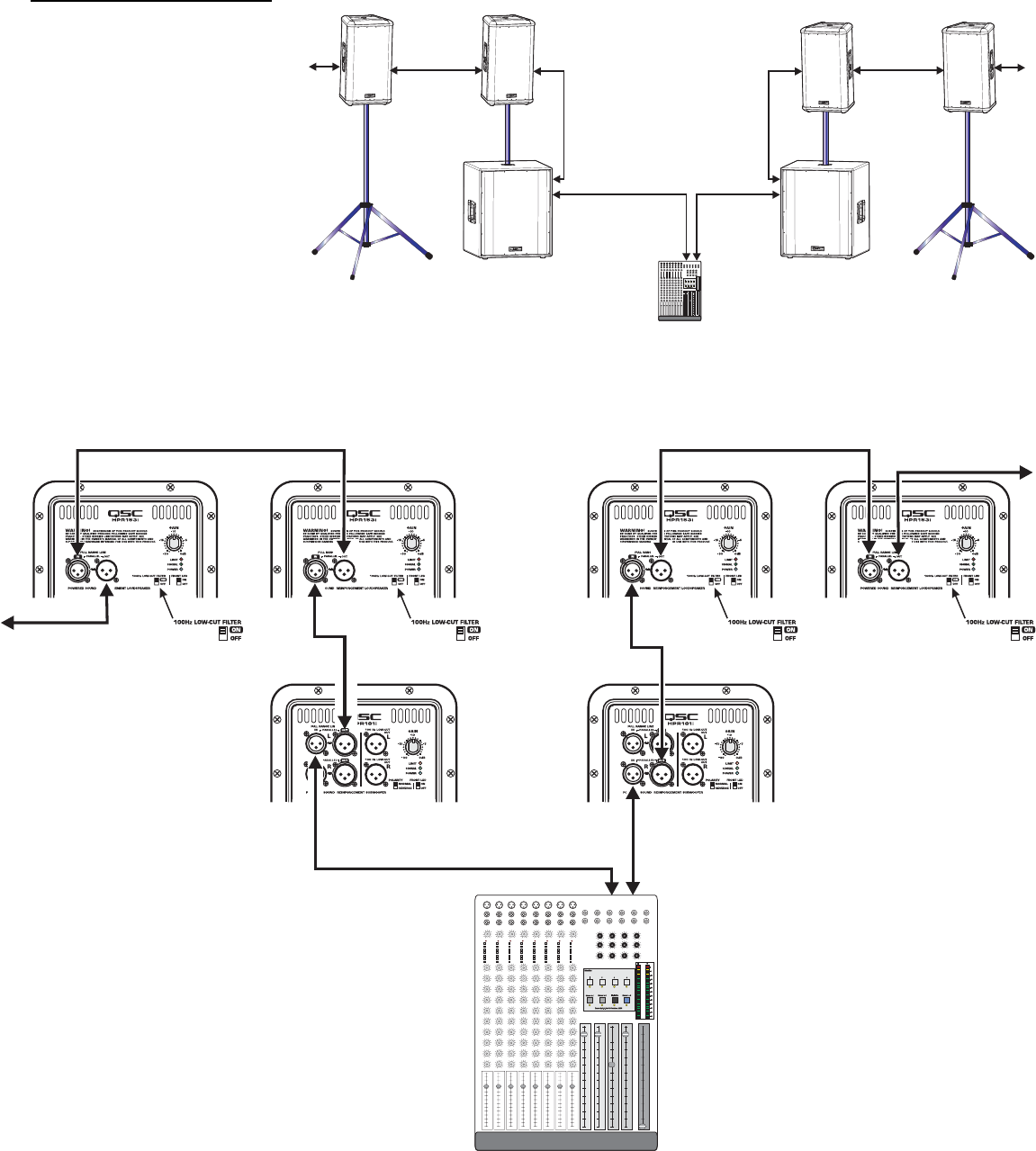
Application Example #4 hookup diagram.
Use only high-quality balanced cables for
interconnecting the audio equipment.
Ensure the top-boxes have their 100 Hz LOW-
CUT FILTER switched on when connecting to
the subwoofer’s FULL RANGE LINE OUT as a
signal source.
Also, be sure to use either the Left or Right
(marked L or R) on the subwoofers. If the sub-
woofer’s input is connected to the Right (R)
channel connector and the output to the top-
boxes is connected to the Left (L) channel
connector, no signal will reach the top-box
(no sound from the top-box).
Mixer or Other Audio Source
Channel 1
or
Left Channel
Channel 2
or
Right Channel
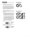
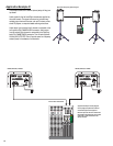
Application Example #4
This example shows a two-channel
(stereo) setup utilizing two sub-
woofers and multiple top-boxes.
This is the same as Application
Example #3 except an additional
top-box has been added to each
channel (and more could be added).
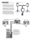
To connect to additional top-boxes,
connect a cable from the last top
box’s FULL RANGE LINE OUT con-
nector to the next top-box’s FULL
RANGE LINE IN connector. Up to 20
top-boxes could be “daisy-chained”
without degrading signal quality.
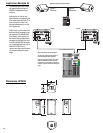
HPR151i or HPR181i
HPR122i, HPR152i, or HPR153i
HPR122i, HPR152i, or HPR153i
Application Example #4 physical diagram.