


9
Rigging the Installation Line Array (continued)
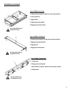
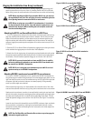
3- Lower the array frame onto the enclosure, carefully aligning the rigging straps, and
attach the top enclosure to the array frame by installing the ball-lock pins or M8 bolts.
Before lifting, ensure the audio connection to the enclosures are correct and functioning.
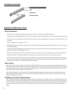
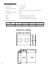
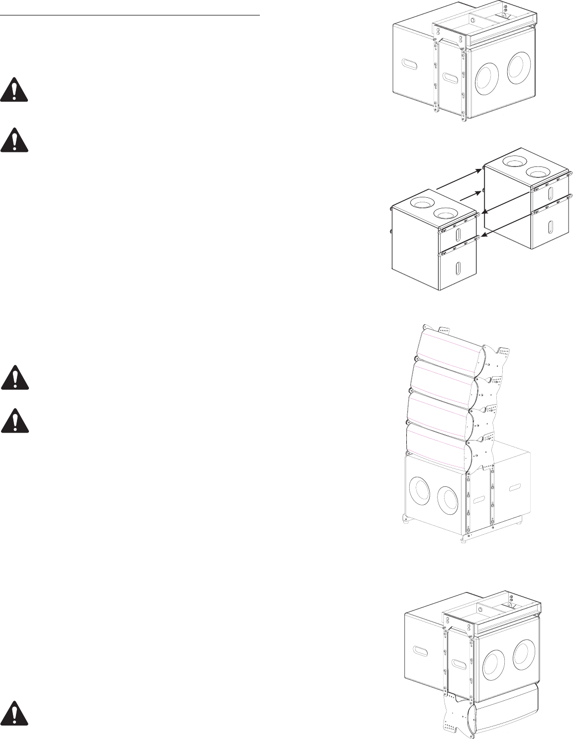
NOTE: When attaching one WL115-sw to another WL115-sw, you must use
the supplied ball-lock pins. This will allow for easier installation given the
close spacing between consecutive WL115-sw enclosures.
NOTE: When arraying two or more WL115-sw subwoofers, it is easiest to
lay the enclosures on their backs, align and mate the rigging straps, and
install the ball-lock pins. When installing the ball-lock pins, ensure full
insertion and locking action.
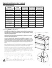
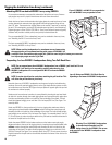
Attaching the GS115-sw Ground Stack Rails to a WL115-sw
1- For all four rigging straps: Using an 6mm hex wrench, remove the upper and lower rig-
ging strap retaining bolts and loosen the two bolts in between. Pull the inner and outer
straps to their outermost position; pull the center strap to its outermost position, and
align the retaining bolt holes with the threaded inserts of the enclosure. Re-install the
outermost rigging strap retaining bolts and tighten all four bolts on each strap to 13 lb-ft
(17.6 N-m).
2- Position a GS115-sw Ground Stack rail between the rigging straps on the right and one
to the outside of the rigging straps on the left side of the loudspeaker.
3- Attach the rail to the rigging strap by inserting the cap-head shoulder bolt with washer
through the mated components and threading the lock nut (nylock) on the inside edge of
the assembly. The bolt should be tightened snuggly to no more than 5 lb-ft (6.8 N-m).
NOTE: GS115-sw must be attached to at least one WL115-sw for stability
before any additional loudspeakers are attached. GS115-sw should never
be attached to a WL2082-i loudspeaker.
NOTE: GS115-sw is designed to accommodate up to two WL115-sw loud-
speakers and up to six WL2082-i loudspeakers.
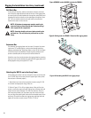
Attaching WL2082-i enclosures beneath WL115-sw enclosures
For arrays of 4 WL2082-i loudspeakers or less, assemble the WL2082-i loudspeakers on
the ground using the included mating hardware. Ensure the notched rigging plate is on the
right hand side (the system can only be installed one way; the QSC logo on the input plate
will appear right side up when the enclosure is oriented properly). During assembly,
ensure your splay angles are as desired.
When constructing large arrays it is recommended to first assemble units of four enclo-
sures and then assemble the final array by joining the four enclosure units to one another.
Attachment of one enclosure to another is accomplished by inserting the cap-head shoul-
der bolt with washer through the mated rigging plates and appropriate splay angle selec-
tion holes and threading the lock nut (nylock) on the inside edge of the plates. The bolt
should be tightened snuggly to no more than 5 lb-ft (6.8 N-m). See Figure 7 for assembly
detail.
Lower the array frame with subwoofer(s) onto the WL2082-i enclosure cluster and attach
the top enclosure to subwoofer by inserting the cap-head shoulder bolt with washer
through the mounting holes and threading the lock nut (nylock) on the inside edge of the
plates and rigging straps.
NOTE: See Pull-Back Bar and Extension Bar sections on previous page for
information regarding their use.
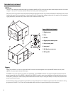
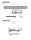
Figure 14: WL2082-i attached to WL115-sw and FB2082-i.
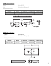
Figure 13: GS115-sw Ground Stack Rails attached to
WL115-sw.
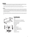
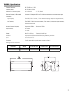
Figure 11: WL115-sw attached to FB2082-i.
Figure 12: WL115-sw to WL115-sw rigging.