


EN
5
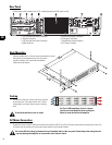
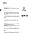
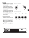
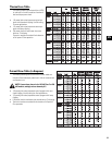
Stereo Mode - Switches 4, 5, 6
and 7 are all set to the DOWN
position.
Parallel Mode - Switches 4, 5,
and 6 are set to the UP position.
Switch 7 is set to the DOWN
position.
Bridge Mode- Switches 4, 5, 6
and 7 are all set to the UP posi-
tion.
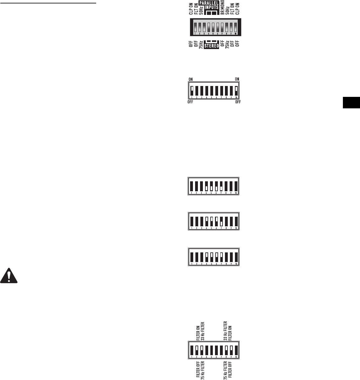
Low Frequency Filter (“V” model
shown): Each channel has its
own switches for LF filter on/off
and frequency selection.
•The first channel uses switches
2,3. The second channel uses
switches 8,9.
•Switches 3 and 8 turn the LF fil-
ter ON or OFF.
•Switches 2 and 9 select 33/75 Hz
(low Z) or 50/75 Hz (“V” models)
or 75 Hz.
•On four-channel models, the
second mode switch has
switches for Ch.3 and Ch.4
Setting the Mode Switches
Two-Channel Models: One mode switch controls each channel’s indepen-
dent clip limiting and low frequency (LF) filtering. The switches can set the
amplifier’s operating mode for Stereo, Parallel, or Bridge operation.
Four-Channel Models: There are two mode switches; one controls the
operation of channels 1-2, the other controls the operation of channels 3-4.
It is not possible to bridge or parallel channels 1 or 2 with channels 3 or 4.
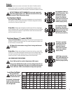
Setting Clip Limiters
Each channel has a clip limiter with its own on-off switch. The limiter only
responds to actual clipping, and automatically compensates for load and
voltage variations. Clip limiting is generally recommended, especially to
protect high frequency drivers.
Set switch UP (ON position) to use Clip Limiting.
Switch 1 controls the first channel.
Switch 10 controls the second channel.
Selecting Stereo, Parallel, or Bridge Mode
Each of the channel pairs can be set for normal Stereo operation, Parallel
Input mode, or Bridge Mono mode. On four-channel models, Ch.1 can be
bridged or paralleled with Ch.2; Ch.3 can be bridged or paralleled with Ch.4.
Stereo Mode- Each channel within the pair remains independent, and
each may be used for a different signal.
Parallel Mode - This setting connects both inputs of a pair together. One
signal feeds both channels. Do not connect different sources to each input.
Each channel's Gain control and speaker connection remain independent.
Bridge Mode- This setting combines both channels of a pair into a single
channel with twice the output voltage. Use only the first channel's input
and Gain control. Set the second channel's Gain control at minimum.
Do not connect different inputs to each side of a channel pair
when operating in parallel or bridge mode.
Setting Low Frequency Filters
Each channel has a 12dB per octave Low Frequency filter that can be set on
or off. Low impedance models can be set for 33 or 75 Hertz and distributed
output (“V” models) for 50 or 75 Hertz to prevent saturation of the 70V
speaker transformers. This reduces distortion and prevents amplifier over-
load.
Low Impedance Models: The filter should only be turned off for driving
subwoofers. The 33 Hz setting usually works well with loudspeakers that
have large LF drivers (12” or larger). The 75 Hz setting works well with com-
pact (smaller size) loudspeakers. Check the loudspeaker’s specifications and
select the setting closest to the loudspeaker’s low frequency capability.
High Impedance (“V”) Models: The filter should only be turned off for
driving subwoofers with special low frequency transformers. The 50 Hz set-
ting usually works well with high quality speaker transformers. The 75 Hz
setting works well with speech-grade speakers and transformers.
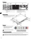
Each channel has its own switch
for Clip Limiter on/off.
The first channel uses switch 1.
The second channel uses switch
10. On four-channel models, the
second mode switch has
switches for Ch.3 and Ch.4
Typical Mode Switch block as
seen from the rear of the amplifier
(CX404V model shown).