


EN
6
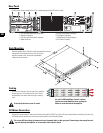
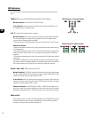
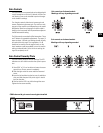
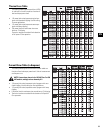
DataPort
Two-channel models have one DataPort, four-channel models have two DataPorts (one Ch.1-2, one for Ch.3-4).
The DataPort connects to optional QSC accessories and processing devices. DataPort devices provide remote
Standby control, monitoring, DSP processing, filter and crossover functions. The CX’s DataPort supports the full
"V1" DataPort feature set. Two-channel models support directly-mounted DSP “modules”. Four channel models
require remote mounting of accessory modules connected with DataPort cables.
Each DataPort connects to its respective channel pair; Ch.1-2 or Ch.3-4. Each channel pair may use its DataPort
or the Terminal Block inputs. When using the DataPort, do not connect to that channel's Terminal Block inputs.
Amplifier Standby is controlled only by the Ch.1- 2 DataPort.
DataPort Tips:
1- DataPort 1-2 controls Standby for the entire amplifier. The AC switch must be turned ON before the DataPort
can control the power.
2- Each DataPort controls and monitors the signals to its respective channel pair (Ch.1-2, Ch.3-4).
3- Do not use the Bridge Mono or Parallel mode switches when using DataPort Inputs. The signal level may be reduced. For more infor-
mation, see the Owner's Manual for the DataPort device.
4- A DataPort device is normally used to control the signal gain before entering the amplifier. Set the front panel Gain controls at max-
imum after confirming correct operation. If desired, install the protective cover to prevent tampering.
5- Each channel uses a separate internal heat sink. The heat sink temperatures are reported on that pair's DataPort.
6- Consult your QSC dealer or the QSC web site for the latest DataPort products.
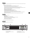
Inputs
Each channel has a balanced 3-pin terminal block input. Two channel models also feature XLR inputs. The input impedance is 12k ohm
balanced or 6k ohm unbalanced. A set of terminal block connectors is included in the carton. Terminal block wiring is connected with
simple hand tools, and inputs can be changed quickly. XLR inputs are connected with standard cables and can be changed quickly.
Pinouts are marked on the rear panel.
Balanced connections are recommended to reduce AC hum and interference, especially with long cable runs. Unbalanced connections
may be suitable for short cables. The signal's source impedance should be less than 600 ohms. If the DataPort is being used for input
signals, do not connect cables to the terminal blocks.
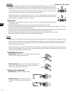
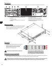
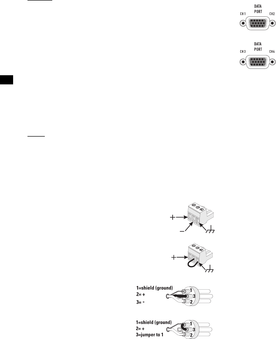
Terminal Block Connectors
Balanced inputs: Strip the wires ¼ inch (6mm) and connect to the plug
as shown. Be sure to tighten the screws firmly.
Unbalanced inputs: Strip the wires ¼ inch (6mm) and connect to the
plug as shown. The middle pin must be connected to the shield pin as
shown. Be sure to tighten the screws firmly.
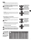
XLR Inputs (2-Ch. models only)
Balanced inputs: Connect to the plug as shown.
Unbalanced inputs: Connect to the plug as shown.
Pin 3 and pin 1 must be connected with a jumper as
shown.
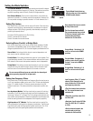
DataPorts on a 4-Ch. amplifier.