


EN
5
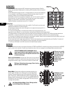
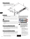
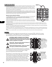
Stereo Mode - Switches 4, 5, 6
and 7 are all set to the DOWN
position.
Parallel Mode - Switches 4, 5,
and 6 are set to the UP position.
Switch 7 is set to the DOWN
position.
Bridge Mode- Switches 4, 5, 6
and 7 are all set to the UP posi-
tion.
Each channel has its own
switches for LF filter on/off and
frequency selection.
The first channel uses switches
2,3. The second channel uses
switches 8,9. Switches 3 and 8
turn the LF filter ON. Switches 2
and 9 select 50Hz or 75 Hz
SELECTING STEREO, PARALLEL, OR BRIDGE MODE
Each of the four Channel Pairs can be set for normal Stereo operation, Parallel Input mode, or Bridge Mono mode.
Stereo Mode- Each channel within the pair remains independent,
and may be used for two different signals.
Parallel Mode - This setting connects both inputs of a pair together.
One signal feeds both channels. Each channel's Gain control and
speaker connection remain independent.
Bridge Mode- This setting combines both channels of a pair into a
single channel with twice the output voltage. Use only the first chan-
nel's input and Gain control. Set the second channel's Gain control at
minimum. The load must be rated for 140V, and is connected as
shown on page 6.
Do not connect different inputs to each side of a channel pair when operating in parallel or bridge mode.
SETTING LOW FREQUENCY FILTERS
Each channel has a 12dB per octave Low Frequency filter
to prevent saturation of the 70V speaker transformers.
This reduces distortion and prevents amplifier overload.
The filter should only be turned off for driving subwoofers
with special low frequency transformers. The 50 Hz set-
ting usually works well with high quality speaker trans-
formers. The 75 Hz setting works well with speech-grade
speakers and transformers.
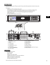
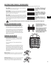
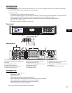
TERMINAL BLOCK INPUTS
Each channel has a balanced 3-pin input. A full set of
mating connectors is included in the carton. Wiring is
connected with simple hand tools, and inputs can be
changed quickly.
The input impedance is 12k ohm balanced or 6k ohm
unbalanced.
Balanced connections are recommended for less AC hum
and interference, especially with long cable runs. Unbal-
anced connections may be suitable for short cables. The
signal's source impedance should be less than 600 ohms.
If the DataPort is being used, do not connect cables to the
terminal blocks.
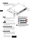
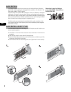
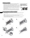
Balanced inputs: Strip the wire ¼ inch (6 mm) and connect
to the plug as shown. Be sure to tighten the screws firmly.
Unbalanced inputs: Strip the wire ¼ inch and connect to the
plug as shown. The middle pin must be connected to the
shield pin as shown. Be sure to tighten the screws firmly.