


6
Rigging (continued)
NOTE: All hardware/components must be rated for the
expected loads as determined by the Professional Engi-
neer responsible for suspension.
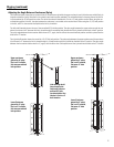
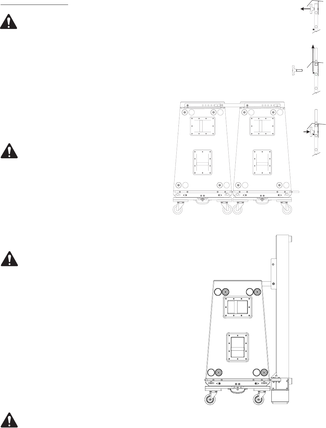
Attaching WL218-sw Loudspeaker to WL218-sw Loud-
speaker
1- With the enclosures on dolly boards and facing downward, posi-
tion two enclosures adjacent one another such that the front receiver
tubes are aligned.
2- Unpin and extend the articulated joints from the lower enclosure.
Align and insert the articulated joint into the upper enclosure’s
receiver tube. Pin each articulated joint in place using two ball lock
pins, one at each end inserted fully and locked in position. Ensure all
four (4) pins are used and locked securely into place. Replace any
faulty or questionable ball lock pin immediately.
Failure to follow these recommendations may result in
dangerous
conditions, injury, or death!
3- If suspending the array, DO NOT PIN THE REAR LINK ASSEMBLY AT
THIS TIME. The rear links should be pinned with their respective ball
lock pins as the array is hoisted.
Attaching Frame Feet to AF218-sw Array Frame
(0ptional)
With the frame lying flat, attach the frame feet by inserting the button
head screw through the corresponding mounting hole and lock nut.
Tighten fully.
NOTE! Frame feet are for support during installation only.
Frame is unstable when vertically oriented on frame feet.
Do not drop frame on to frame feet when loading and
unloading. Do not leave unattended under any conditions.
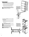
Attaching WL218-sw Loudspeaker to AF218-sw Array
Frame
1- The enclosures to be suspended should be pinned together at the
FRONT left and right receiver tubes as outlined above.
2- Unpin and extend the top enclosure’s articulated joints and pin into
place.
3- The AF218-sw array frame should be positioned so that the top
enclosure’s articulated joints can be inserted into the AF218-sw and
pinned into place. Position the AF218-sw and pin the top enclosure’s
articulated joints into to AF-218-sw’s receiver tubes.
4- Position the AF218-sw array frame so its rear link may be pinned
into the top enclosure’s receiver block at the desired location. Pin the
link into the top enclosure ensuring the pin is fully inserted and locked
in place.
NOTE! The marked splay angle location where the AF218-
sw’s link is pinned is the splay angle between the frame
and the top enclosure (AF218-sw link has 0° offset).
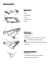
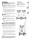
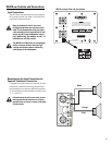
Front Articulated Joint-
1- Remove the ball lock pin.
2- Slide the articulated joint out of the
receiver tube by lifting its retaining screw
upward.
3- Lock in place using the ball lock pin.
1
2
3