


Installation Procedure
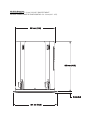
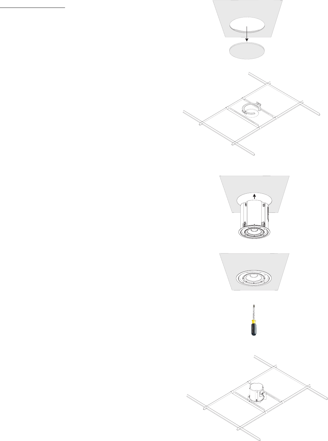
1- Using the included C-ring or the dimensions provided, trace a cutout pattern onto
the ceiling surface.
2- Cut the mounting hole. Use a sharp tool to avoid stressing or cracking the mount-
ing surface.
3- Pull the wires through the hole.
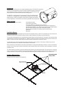
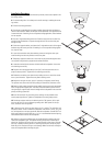
4- Pass the two suspended ceiling support brackets through the hole and place as
shown in the illustration. Make sure the part of the bracket that is flat against the tile
is toward the hole. If installing in a non-suspended ceiling application, these brackets
are not required.
5- Pass the C-ring bracket through the hole. Slide the cutout slot into the hole first,
and then rotate the bracket so it passes through the hole. Be sure the wires pass
through the ring.
6- Position the support brackets, and secure the C-ring bracket to each of the support
brackets using the screws provided. If installing in a non-suspended ceiling applica-
tion, skip this step.
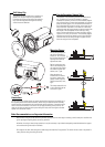
7- Loosen the connection cover plate retaining screw and swing the cover open.
Install an fitting into the hole provided on the cover plate.
8- Temporarily support the enclosure so the wires may be passed through the enclo-
sure top with enough slack to prepare and terminate the wires.
9- Locate the terminal block connectors included with the loudspeaker. Loosen the
wire retaining screws fully.
10- Strip the wire ends approximately 10 mm (0.4”) and insert each wire into its
proper connector position. Tighten the wire retaining screws fully.
11- Rotate the connection cover plate closed, making sure not to stress the connec-
tions or pinch the wires. Tighten the cover plate’s retaining screw.
12- Adjust the wiring at the entry point, if necessary, and properly secure fitting.
This prevents wire stress and strain from pulling the connections/connectors loose.
13- Attach a safety cable (secondary support cable) from the enclosure’s attachment
tab to an appropriate support point. This cable and the attachment points must be
strong enough to support many times the weight of the loudspeaker in the event the
primary mounting system fails.
14- Insert the enclosure into the ceiling cutout, making sure any brackets used
remain properly positioned. Tighten the loudspeaker’s mounting clamp screws.
15- Set the tap selector switch to the desired position. 70V systems, all four posi-
tions may be used. Do not use highest tap setting with 100V systems. 8 ohm sys-
tems, se selector to 8 ohm position.
16- If desired set the 120 Hz low pass filter to the “In” position. This will allow only
frequencies below 120 Hz to reach the loudspeaker. If the switch is in the”‘out” posi-
tion, all frequencies in the input signal will reach the loudspeaker. If the AD-C81Tw is
being used with the low-pass filter set to “out” it is recommended that the input sig-
nal be filtered before it enters the loudspeaker.
17- Make sure all tests and adjustments are complete before installing the grills.
Locate the loudspeaker’s grill. The cabinet and the grill both have a small loop of
plastic line. Using the clip on the grill’s line, attach the grill’s safety loop to the cabi-
net’s loop. Carefully work the grill into its retaining slot and press firmly into place.
Work the grill in slowly and evenly to avoid damage. Make sure all tests and adjust-
ments are complete before installing the grills.