10
EN EN
Abnormal indication:
• Bright red illumination while the amp is being used indicates either thermal muting or a shorted output.
• If the amplifier overheats, the fan will run at full speed, and operation should resume within one minute. Allow the fan to run, and make sure the
amplifier ventilation is adequate.
• A shorted or overloaded output circuit will cause excessive Clip flashing and possible overheating.
• If distortion is audible without a Clip indication, the problem is either before or after the amplifier. Check for damaged speakers or overloaded
signal source. The amplifier Gain control should be in the upper half of its range to prevent input overload.
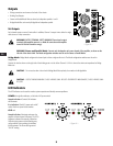
SIGNAL: green, to the left of each Gain control.
Normal indication: illuminates when the input signal exceeds -35 dB. As signal approaches full power, the indicator will illuminate continuously.
If no indication: check Gain settings and increase Gain if necessary. Check input connections and audio source for signal. If the Clip indicator
illuminates with little or no Signal indication, check the output wiring for shorts.
Abnormal indication: If the Signal indicator illuminates with no signal input, there may be system oscillations or some other malfunction. Disconnect
the load and fully reduce the Gain. If the signal indicator remains on, the amp may need servicing.
PROTECT: red, on the right side of Gain control group. (Not available on the 2RU Units)
Normal indication: illuminates when the amplifier goes into protective muting. Under normal operation, this indicator will not be illuminated.
Abnormal indication: If the Protect indicator illuminates, the amplifier is in protective muting. Leave the Power On to allow the fan to cool the
amplifier. Check the rear panel circuit breakers; if either is tripped, reset it by pushing on the center of the control. When the amplifier has cooled
sufficiently, the Protect indicator will extinguish and normal operation will resume.
NOTE:
If both rear panel circuit breakers are tripped, the Protect indicator will not be illuminated.
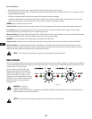
Gain Controls
Turn the Gain controls clockwise to increase Gain and counterclockwise to decrease Gain. At the maximum setting, the voltage Gain of the amplifier is
+36 dB. The RMX 4050a will produce 800 watts into 8 ohms when driven with a 1.26V input signal. The RMX 5050a produce 1050 watts into 8 ohms
when driven with a 1.42V input signal.
The Gain controls are marked in dB of gain.
Settings should normally be made within the
upper half of the adjustment range. The range
below 22 dB should not be used for normal
program levels, as the input headroom could be
exceeded, but can be used for testing at reduced
levels. At the minimum setting, the signal is
completely cut off.
CAUTION!:
Continuous
operation at high power may
trigger the thermal protection circuitry, shutting down the amplifier and fully illuminating the Protect indicator. Operation will resume
after the amplifier has cooled down sufficiently.
NOTE:
If both rear panel circuit breakers are tripped, the Protect indicator will not be illuminated.
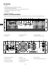
— Figure 14 —


