


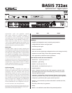

BASIS 722az
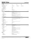
Specifications
qscaudio.com
Specifications subject to change without notice.
1675 MacArthur Boulevard • Costa Mesa, CA 92626 • Ph: 800/854-4079 or 714/957-7100 • Fax: 714/754-6174
BASIS 722az - 06/17/08
PERFORMANCE
Dynamic Range (AES-17, -60 dB method, all sensitivities) In Out Thru
Unweighted > 115 dB > 112 dB 110 dB
A weighted > 118 dB > 115 dB 113 dB
Distortion (20 Hz – 20 kHz, all sensitivities)
+4 dBu (maximum) < 0.009% THD+N < 0.009% THD+N < 0.009% THD+N
2 dB below clip (maximum) < 0.009% THD+N < 0.009% THD+N < 0.009% THD+N
Crosstalk (20 Hz – 20 kHz)
Inter-channel (maximum) > 75 dB
Inter-channel (typical) > 90 dB
Intra-channel (maximum) > 85 dB
Intra-channel (typical) > 100 dB
Frequency Response
20 Hz – 20 kHz (maximum) +/- 0.5 dB
20 Hz – 20 kHz (typical) +/- 0.2 dB
Audio Converters 24 bit, 48 kHz, in and out
Mute Infinite attenuation
Delay
Analog input through full DSP chain to analog output 2.354 milliseconds (default group delay)
INPUTS/OUTPUTS
Program Inputs 8 inputs
Connector type 3-pin “phoenix style” (a.k.a. “Euro style”) detachable terminal blocks
Type Electrically balanced
Grounding All shield terminals connected to chassis
Pinout 1:+ / 2:- / 3:CHASSIS GND
Input Impedance Balanced: 10k ohms / Unbalanced: 10k ohms
Common-mode Rejection 20 Hz – 20 kHz (minimum): > 54 dB / 20 Hz – 20 kHz (typical): > 60 dB
Input Sensitivities (variable) Vrms: 1.5, 3, 9, 18 / dBu: 5.7, 11.8, 21.3, 27.3 / dBV: 3.5, 9.5, 19.1, 25.1
Program Outputs 8 outputs
Connector Type 4 HD-15 DataPort connections
Cable Type QSC DataPort cable, QSC p-n DPC-x (“x” designates cable length in feet)
Available “Stock” Lengths 1, 2, 3, 4, 5, 6, 10, and 20 ft., custom lengths available
Maximum Qualified Length 328 ft. (100 m) using QSC DP cable only / Non QSC cable limited to 6 ft. (audio only)
MONITOR
Control Room Foldback Monitoring
Connector type 5-pin “phoenix style” (a.k.a. “Euro style”) detachable terminal blocks
Pinout 1:+(input) / 2:-(input) / 3:CHASSIS GND / 4:-(output) / 5:+(output)
Tap Points 8 internal input / 8 internal output / 8 amplifier (pre-, post-, amplifier) software selectable
Monitor Input
Monitor Signal (unit off) Unity gain connection, relay bypass
Maximum Level +21 dBu
Impedance (nominal) 10k ohms
CMRR, 20 Hz – 20 kHz > 54 dB
Monitor Output
Monitor Sum of monitor input and signal from internal monitor tap point(s)
Frequency Response (20 Hz – 20 kHz) +/- 0.5 dB
Distortion (20 Hz – 20 kHz) < 0.05% at +4 dBu
Noise Floor > 90 dB
Output Impedance (nominal) 100Ω
Output Load (minimum) 600Ω
Monitor Level
Control Range (nominal) 0 dB to -95.5 dB in 0.5 dB steps
CONTROL INPUTS/OUTOUTS
Relay Outputs 2 discrete floating relay switch outputs
Connector Type 3-pin “phoenix style” (a.k.a. “Euro style”) detachable terminal blocks
Configuration Electromechanical relay
Pinout 1:NC / 2:NO / 3:COM
Switching Capacity (nominal) 1A 30 VDC
Logic Outputs 4 discrete outputs
Connector Type 2-pin “phoenix style” (a.k.a. “Euro style”) detachable terminal blocks
Configuration Single-ended, TTL compatible
Pinout 1:+(Signal) / 2:-(CHASSIS GND)
Omni Inputs 6 discrete inputs for TTL logic, voltage control or passive resistance
Connector Type 2-pin “phoenix style” (a.k.a. “Euro style”) detachable terminal blocks
Configuration Single-ended, ground referenced
Pinout 1:+(Signal) / 2:-(CHASSIS GND)
Normal Operating Range Reads signals between 0-5 V nominally
Potentiometer Operation Use 10k ohms for full range
Voltage Tolerance +/- 48 V
Current Output 0.5 mA with 10k pot (for passive resistive controls)
RS-232 Port Female DB9 connector (setup and diagnostics purposes only)
QSControl Port Neutrik Ethercon RJ45 ruggedized data connector
Indicators
QSControl Status Yellow Link, Tx, Rx, front panel / Green Link, Tx, Rx, rear panel
Power Blue, front panel
Diagnostic Red, front panel
DataPort Status (port) Tri-state (red, green, yellow), front panel
LCD Data Display 2 line x 16 character, backlit, front panel