


SPECIFICATIONS
ARCHITECT’S AND
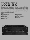
MODEL 3800
OUTPUT POWER (per channel)
Continuous Average Output Power Bridged-mono operation.
both channels driven 16 ohms, 20–20kHz, 0.1% THD 720
8 ohms, 20–20kHz, 0.1% THD 375 1 kHz, 1% THD 880
1 kHz, 1% THD 440 8 ohms, 20–20kHz, 0.1% THD 1,200
4 ohms, 20–20kHz, 0.1% THD 600 1 kHz, 1% THD 1,500
1 kHz, 1% THD 750 4 ohms, 20–20kHz, 0.2% THD 1,700
2 ohms, 20–20kHz, 0.2% THD 850 1 kHz, 1% THD 2,200
1 kHz, 1% THD 1,100
DISTORTlON (8 ohms) THD: 20–20kHz at rated power shall be less than 0.1%
SMPTE-IMD: less than 0.025% at rated power
FREQUENCY RESPONSE 20–20kHz, ±0.1dB
8–300kHz, +0/-3dB
DAMPING FACTOR Greater than 200
DYNAMIC HEADROOM 2dB at 4 ohms
NOISE
SENSITlVlTY
INPUT IMPEDANCE
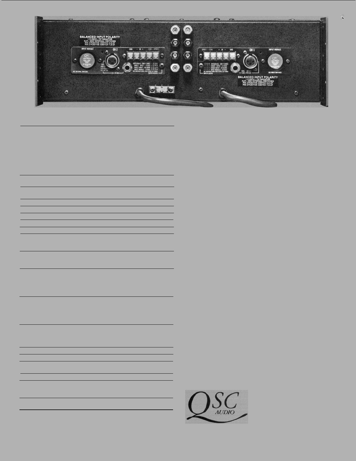
CONTROLS
-100dB 20–20kHz at rated power
1V RMS for rated power at 8 ohms
20K balanced or 10K unbalanced
Front: Recessed detented gain control, AC switch/circuit
breaker far each channel.
INDICATORS
(per channel)
COOLING
Rear: Mono-bridging and input accessory module switches.
Bicolor LED indicating DC power, OK/Protect mode, LED clip
indicator, -30dB and -6dB signal level indicators, flashing
overtemp indicator.
Passive-combined with high-efficiency output stage for 50%
reduction in dissipated heat. Unique circuit configuration provides
direct-metal mounting of output devices to minimize short-term
thermal excursions of power transistors. Fan-assisted cooling
recommended for
high
duty cvcles at 2 ohms.
AMPLIFIER PROTECTION
LOAD PROTECTION
lndefinite short-circuit* open-circuit, over-temp, ultrasonic and
RF protection. Stable into reactive and mismatched loads. Inputs
protected from overload
*Output Averaging™ Short Circuit Protection
(US Patent 4,321,554)
lndividual channel output relays provide DC Fault, 3 second
delayed turn-on (transient protection), and excessive Iow-
frequency protection. Instant turn-off, pop suppression and power
interrupt protect is also provided.
OUTPUT TYPE
OUTPUT DEVICES (total)
POWER SUPPLIES
POWER REQUIREMENTS
DIMENSIONS
WEIGHT
Full complementary two-level high efficiency
40
A complete separate power supply for each channel including
AC switch/circuit breaker and AC cord.
120, 220, or 240V 50–60 Hz, 13A (each channel)
Faceplate 19"x5.25"
Depth 17.9" (with rear supports)
15.9” (chassis only)
75 Ib. (Net)
83 Ib. (Shipping)
Specifications subject to change without notice.
ENGINEER’S SPECIFICATIONS
The amplifier shall contain all solid-state circuitry, using complementary silicon transistors and
integrated circuits It shall be capable of operating from 120, 220 or 240V 50–60Hz AC mains
with internally selectable jumpers.
The amplifier shall contain two fully independent channels, with separate AC breaker/switches,
power transformers, and protective systems. Each channel shall have independent protective
circuitry against open-circuit, short-circuit or mismatched loads; independent thermal warning
and shutdown circuits, and independent load protection circuits for turn on/off transients includ-
ing momentary AC dropouts and DC faults within or preceding the amplifier All protective cir-
cuits except AC circuit breaker shall be self-resetting. The remaining channel shall continue to
operate, in stereo or bridged-mono mode.
Each channel of the amplifier shall be capable of meeting the following performance criteria,
with both channels driven simultaneously.
Output power into 8 ohms 375 watts, 20–20kHz, less than 0.1% THD.
Output power into 4 ohms 600 watts, 20–20kHz, less than 0.1% THD.
Output power into 2 ohms 850 watts, 20–20kHz, less than 0.2% THD.
Frequency response shall be 20–20kHz, with less than 0.1 dB deviation.
The voltage gain shall be 34.5dB at full Gain.
The power gain (into 8 ohms) shall be 65.5 dB at full gain.
The input sensitivity for rated 8-ohm power shall be 1V RMS.
Balanced bridging input circuitry shall be standard, and the amplifier shall meet all performance
criteria in the balanced or unbalanced mode.
Input impedance shall be 20k ohms balanced, or 10k ohms unbalanced.
Noise level shall be at least 100dB below rated power, at full Gain.
IHF damping factor shall exceed 200.
The amplifier shall be passively cooled, with no fans or moving parts.
Each channel shall have the following controls, functions, and indicators:
31-detent Gain control, with 1 dB steps over the highest 14dB of adjustment range, with
accuracy within 1 dB;
Green/Red LED for power/protect indication;
Yellow LED signal presence indicators with thresholds 6dB and 30dB below rated power.
Red LED clipping indicator for output clipping greater than 0.1%;
Flashing red LED indicator for heat sink temperatures within 10°C of thermal shutdown.
Balanced/Unbalanced input jacks of the ¼ inch RTS, female XLR, and barrier strip screw
terminal types;
Speaker connectors comprising two sets of 5-way bindlng posts on ¾-inch centers and barrier
strip screw terminals.
Octal socket with DC power for passive and active input accessories.
8-way microswitches for octal socket bypass, mono-bridged mode, channel cross-connection,
and XLR input polarity.
Each channel shall be front-removable with the amplifier mounted in a rack and without dis-
connecting the input/output cables. All active components, except AC power transformer, AC
breaker/switch, and input/output connectors, shall be mounted on the removable channel mod-
ule. Module connectors shall be flexible to withstand shocks and vibration for long term integrity.
The chassis shall feature permanently attached AC cords, and a ground-lift barrier strip shall
permit separation of audio ground from chassis/AC ground.
The chassis shall have front and rear rack supports, and shall occupy 3 rack spaces (5.25")
Chassis depth, including rear supports, shall be 17.9". Weight shall be 75 Ib.
The power amplifier shall be the QSC Audio Products Model 3800.
QSC AUDIO PRODUCTS INC
1926 PLACENTIA AVENUE
COSTA MESA, CA 92627
714-645-2540