


OPERATION
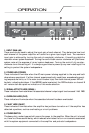
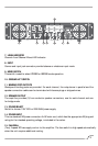
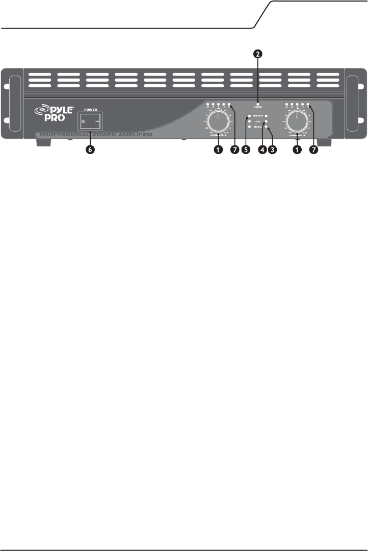
1. INPUT GAIN (dB)
These controls are used to adjust the input gain of each channel. They determine how loud
each channel of the power amplifier will sound for a given input signal level. The maximum
input gain is achieved by turning the control completely clockwise - this setting yields the
maximum mixer/system headroom. Turning the control back counter-clockwise will yield lower
system noise at the expense of mixer/system headroom. Turning the control fully counter-
clockwise turns this setting off. It is always a good idea to power up any new installing at this
setting to protect the system loudspeakers.
2. POWER LED (POWER)
These indicators illuminate when the AC main power is being supplied to the amp and both
channels are operational. If either channel experiences faulty conditions, exceeds safe operat-
ing temperature limits, or if the main circuit breaker trips, then both channel power LED will
be dark, indicating shutdown. If the BRIDGE mode is selected, the PWR indicator on channel B
will remain dark as a positive indication of this mode selection.
3. SIGNAL ACTIVITY LEDS (SIGNAL)
These indicators illuminate when the associated channel output signal level exceeds 1 Volt RMS.
4. OVERLOAD LEDS (CLIP)
These indicators illuminate when the associated channel has been overloaded.
5. FAULT LEDS (FAULT)
These indicators illuminate when the amplifier has just been turned on or if the amplifier has
detected a problem, such as overheating or circuit problems.
6. POWER SWITCH
This heavy-duty, rocker-type switch turns on the power to the amplifier. When the unit is turned
on, there is a three-second delay, which reduces/eliminates the turn-on transients associated
with the system equipment connected to the amplifier and protects loudspeakers.