


PROTECT
MIN MAX
CLIPSIG
CHANNEL 1
CHANNEL 2
CLIP SIG
MIN MAX
POWER
CAUTION:
FOR CONTINUED PROTECTION AGAINST RISK OF FIRE
REPLACE ONL
Y WITH SAME TYPE FUSE.
DISCONNECT SUPPLY CORD BEFORE CHANGING FUSE.
CAUTION:
-30 -20 -15 -10 -5 0 +3
-30 -20 -15 -10 -5 0 +3
POWER
CLIPSIG
SIG CLIP
PROTECT
PROTECT
ON
OFF
1 Features and Controls, PZR6XA/10XA and PZR30XA/50XA
2 Installation Guidelines
2 Input Connections
2 Connecting a CD, DVD or tape player or tuner
2 Connecting an equalizer or signal processor
2 Stereo or Mono Inputs
2 Speaker connecitons
3 Bridged Mode Operation
4 Connecting to standard AC power
4 Mounting the amplifier
4 Turning the amplifier on
4 Using the power LED meter
4 Caring for your Pyle Pro Amplifier
4 Using the channel1 and channel2 output level controls
4 About the internal clip circuitry
5 Specifications
5 Limited warranty
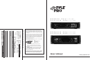
TABLE OF CONTENTS
Please read this manual throughly before you attempt to set up and use the amplifier. It contains a
range of installation suggestions as well as instructions to ensure safe usage. Installed properly, you
can expect years of trouble-free service from this product.
PYLE PRO PZR6XA/10XA/30XA/50XA Amplifier
Owner’s Manual – 1
PYLE PRO PZR6XA/10XA/30XA/50XA Amplifier Owner’s Manual
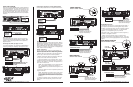
FEATURES AND CONTROLS
Protection Circuit and Indicator
The indicator will be illuminated when
the amplifier is powered on and at turn-
on delay status; the indicator will be
turned off after internal outputs are
connected. The indicator will also be
illuminated when the amplifier has
abnormal problems, such as overload
or excessive heat.
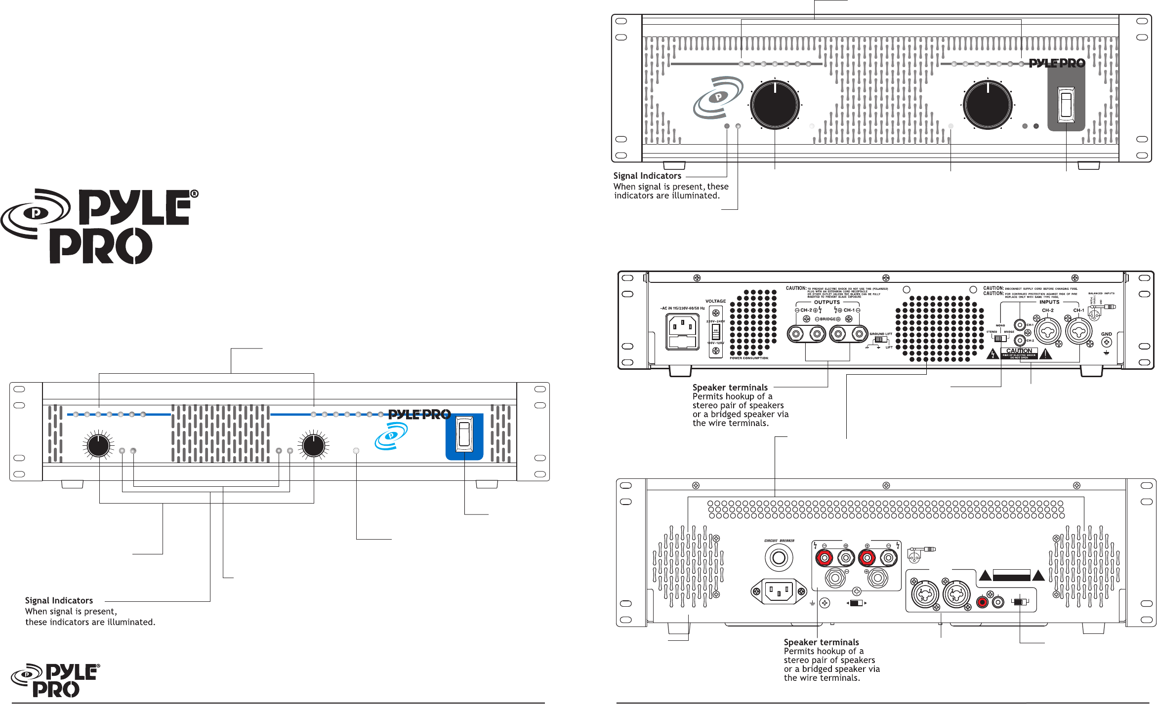
FEATURES AND CONTROLS
FRONT PANEL, PZR30XA/50XA
FRONT PANEL, PZR6XA/PZR10XA
Channel 1 and Channel 2
Output Level Controls
Lets you adjust the sound levels
for each channel.
Clip Circuit and Indicator
This special circuitry protects
the amplifier and speaker system
from being damaged by
overdriving power levels.
Indicator lights remind the user
to reduce the volume when
amplifier output is excessive.
Channel 1 and Channel 2 Power LED Display
Indicate the output signal level for each channel.(
PZR6XA without
)
Power On/Off
Protection Circuit and Indicator
The indicator will be illuminated when
the amplifier is powered on and at turn-
on delay status; the indicator will be
turned off after internal outputs are
connected. The indicator will also be
illuminated when the amplifier has
abnormal problems, such as overload
or excessive heat.
Channel 1 and Channel 2
Output Level Controls
Lets you adjust the sound levels
for each channel.
Clip Circuit and Indicator
This special circuitry protects the amplifier and speaker system
from being damaged by overdriving power levels. Indicator lights
remind the user to reduce the volume when amplifier output is
excessive.
Power On/Off
Your New Pyle Pro PZR series P.A.
Amplifier gives you the power and
versatility you need in a professional
sound system.
The amplifier's wide frequency
response makes it suitable for
amplifying music or vocal program
material. It can be used for live bands,
office paging systems, public
announcements, or a variety of other
installations.
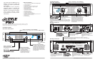
REAR PANEL, PZR6XA/10XA
Fan Cooling
Cooling system is automatically activated whenever amplifier is turned on.
This forced air cooling system rapidly exhausts interior heat, reducing operating
temperature and aiding performance.
Stereo/Mono Switch
Lets you select conventional
stereo operation with a
stereo input signal or bridged
mono input mode.
Input Jacks
Let you connect a variety of audio
input sources via the balanced
(XLR/6.35mm phone jack
combinations) or unbalanced (RCA)
inputs.
REAR PANEL, PZR30XA/50XA
Fan Cooling
Cooling system is automatically activated
whenever amplifier is turned on. This forced
air cooling system rapidly exhausts interior
heat, reducing operating temperature and
aiding performance.
Stereo/Mono Switch
Lets you select conventional
stereo operation with a stereo
input signal or bridged
mono input mode.
Input Jacks
Let you connect a variety of audio
input sources via the balanced
(XLR/6.35mm phone jack
combinations) or unbalanced (RCA)
inputs.
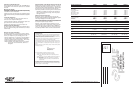
CH-2 CH-1
CH-2 CH-1
OUTPUTS
CH-2
GND
CA
UT
ION
TO PREVENT ELECTRIC SHOCK DO NOT USE THIS (POLARIZED)
PLUG WITH
AN EXTENSION CORD RECEPTACLE
OR OTHER OUTLET UNLESS THE BLADES CAN BE FULLY
INSERTED TO PREVENT BLADE EXPOSURE
CAUTION:
BRIDGE
CH-1
GROUND LIFT
GROUND LIFT
INPUTS
MONO
STEREO BRIDGE
12
3
HOT(+)
COLD(
-
)
GND(+)
BALANCED INPUTS
RISK OF ELECTRIC SHOCK
DO NOT OPEN
Channel 1 and Channel 2 Power LED Display
Indicate the output signal level for each channel.
AC 120V 60HZ
~
ON
OFF
CHANNEL 2
MIN MAX
CHANNEL 1
MIN MAX