


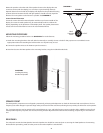
Mount the speaker so that the side of the speaker closest to the display does not
come into contact with the display (2- to 3-inches is a good working distance).
Optimal distance from the side of the display will depend on the predicted listening
position. Distance between the left and right speakers should as closely equal the
distance from one speaker to the listener as possible. See DIAGRAM 2.
Center Channel Placement
Center the center channel horizontal speaker with the top or bottom width of the
display. The center channel speaker may be mounted either above or below the
display, depending on the placement of the display itself. The speaker placement is
closest to the level of the listener’s ears is the recommended choice.
MOUNTING PROCEDURE
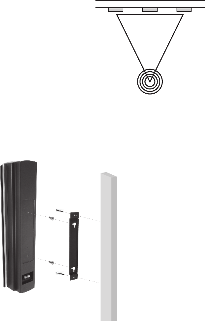
Follow the mounting procedure below. Use DIAGRAM 3 for visual reference.
1. Attach the mounting bracket to the wall, either horizontally or vertically. Screws or bolts for this purpose are not included. Use an
appropriate method for attaching the bracket either to a drywall cavity or stud.
2. Connect the speaker wires to the F400 rear panel connectors.
3. Attach and secure the F400 speaker to the mounting bracket, using the included bracket bolts.
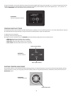
SPEAKER FRONT
The F400 speaker components are configured symmetrically, achieving wide dispersion on both the horizontal and vertical planes. The low-
frequency bass reflex design incorporates large radius port flares for lower turbulence, allowing closer proximity of the listener to the speaker.
The 1” pivoting tweeters can be positioned for optimal directivity. Low- and high-frequency contour switches allow ±3dB fine tuning of indi-
vidual speaker frequency response. See sections, Pivoting Tweeter Adjustment and Contour Switch Settings, respectively, for more informa-
tion.
REAR PANEL
The real panel contains the F400 Speaker Terminals. Speaker wire should be connected prior to securing the F400 Speaker to the mounting
bracket. Before proceeding, make sure that power to the audio amplifier is switched OFF.
2
DIAGRAM 2
A=B=C
Ideal
Listening
Zone
B C
A
Left Speaker Center Speaker Right Speaker
TOP VIEW
DIAGRAM 3
Installing Mounting
Bracket and Speaker