


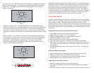
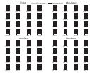

Input Sensitivity - The PAR-224's radio and CD inputs have independently adjust-
able input sensitivity (gain). The gain adjust controls are accessible through the
bottom panel. The diagram below shows the gain provided at various control
settings. (see figure 1)
7
4
3
2
1.5
1
7
Input Gain Control
Figure 1
5V
4V
3V
2V
1V
.5V
Clip Level Control
Figure 2
Input Clip (overload) LED - This indicator lights when the PAR-224's internal
circuitry is overdriven due to improper adjustment of the PAR's input gain controls
or excessive levels coming from the head unit. If the input clip indicator lights
while music is playing, the input gain controls must be set lower (turned counter-
clockwise) or source unit levels must be lowered until the indicator does not come
on.
Output Clip LED - This indicator can be used to show when the overall system
has reached it's maximum power level. It monitors the PAR-224's output level,
which relates to amplifier output. The level at which the indicator activates is
adjustable to match amplifier's maximum level. The control is accessible
through the bottom panel. The diagram below shows the sensitivity match at
various control settings. (see figure 2)
Note that if an electronic crossover or other accessory is connected between
the PAR-224 and an amplifier, the gain of the crossover / accessory will affect
clip indicator setting. A "fine tuning" adjustment should be made so that the
LED comes on just at the volume level where distortion becomes audible
(the next section details the procedure to adjust this control). The indicator
is peak responding, and once triggered it will stay on long enough to be noticed
no matter how briefly the maximum level is exceeded. This way, the user is
warned of the possibility of distortion before it becomes serious.
System Gain Adjusts
In order to achieve maximum signal-to-noise performance from a high quality
stereo system, it is desirable to use high level signals wherever possible in the
inter-connecting cables. High signal levels will reduce the effect of noise
induced into these cables. The peak level of audio signal is usually determined
by the clipping level of electronic components. The following procedure should
be used as a guide after the system installation is complete and ready for final
adjustment.
Adjustment of head unit output and PAR-224 input:
1. Adjust PAR-224 volume control fully counterclockwise
2. Adjust head unit volume to 1/2 - 3/4 of maximum
3. Adjust, if available, head unit line output level to maximum
4 . Set PAR-224 selector switch to radio.
5. Adjust all PAR-224 input gains fully counterclockwise.
6. Play a high quality cassette or FM station if a cassette is unavailable
7. Adjust one of the radio input gains clockwise until input clip light comes on.
Then adjust counterclockwise about 10 degrees. Repeat this step for the
other channel.
8. Set PAR-224 selector switch to CD position and repeat2-7foralternate
source unit.
Adjusting amplifier input gains
1. Adjust amplifier gains to minimum sensitivity. (fully counterclockwise)
2. Adjust the volume knob on the PAR-224 fully clockwise.
3. Increase the gain of the amplifier until the onset of audible distortion.
4. Repeat step 3 for any remaining amplifiers in the system.
Adjusting the output clip indicator
1. Adjust the output clip indicator control fully clockwise.
2. Play system at maximum volume which should be approaching audible
distortion.
3. Adjust the output clip indicator counterclockwise until the indicator comes on.