


p
olarity before securing each wire. If inserting larger gauge wire presents a problem,
tinning the wire with solder may help. Be sure the connection is tight. The connector may
be plugged into the amplifier. (Refer to Figure C)
Bridging
A
ll Art Series amplifiers are capable of being bridged into a mono output due to the
internal design of the amplifier. This feature permits the creation of a mono channel for a
subwoofer or center channel. Also, bridging adds flexibility of operation. Any of the Art
Series two-channel amplifiers can be used in a one channel (mono), two channels
stereo, or 3 channels - 2 channels stereo and one channel mono configuration.
Deriving the mono channel is accomplished by using the left channel positive wire as the
p
ositive speaker wire and the right channel negative wire as the negative speaker wire. I
t
is important that a minimum 4 Ohm impedance is observed. If the impedance drops
below 4 Ohms while the amplifier is wired in the mono configuration, the AM H protection
circuit will en
g
a
g
e.
The ability to run s tereo satellites while simultaneously running a mono output from the
same output stage is accomplished simply by running the stereo speakers normally and
tapping into the appropriate wires for the "Mixed Mono" channel (left channel positive
wire as the positive s peaker wire and the right channel negative wire as the negative
speaker wire). Again, speaker impedance should be 2 Ohms on the stereo channels and
4 Ohms on the mono channel.
Inputs
On the left side panel of the two channel Art Series amplifiers are a set of RCA jacks. A
DIN jack is paralleled to the RCA input and can be used to Phantom Power other PPI
accessories, such as our crossovers and equalizers. The paralleling of these inputs
allow the 'daisy-chaining' of input source to other amplifiers or accessories. Connect
y
our source unit to these in
p
uts.
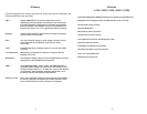
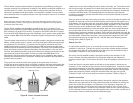
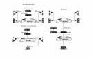
Speaker Connector
Speaker Negative
Speaker Positive
Remote Turn-On
Speaker Positive
Speaker Negative
Figure C: Speaker / Remote Turn-On Connector
Gain Control
On the left end panel, next to the inputs, is the gain control. This control adjusts the level
of the input signal of your source unit. This control requires a small flat blade screwdriver
for adjustment. Upon installation of the amplifier, the gain control must be adjusted. This
can be done by first turning the gain all the way down (counter clockwise). Turn the
volume on the source unit up two thirds. Then adjust the gain control until the desired
volume is obtained without audible distortion.
Low Impedance Indicator
A
MIIcircuitry will lower output power to maintain uninterrupted operation whenever the
amplifier senses an impedance load of less than 2 Ohms. The Low Impedance Indicator
(left-side end panel) is provided to let you know when the amplifier is operating in this
mode. It is important to note that there is no increase in output power below the 2 Ohm
threshold. Maximum power is achieved at 2 Ohms.
In the case of a short circuit, AM II will engage to protect the shorted channel but will
continue to play the unaffected channel. When this occurs, audible distortion will be
heard. Turn-off the system and repair the short. Once the problem has been repaired,
the amplifier will return to normal operation.
System Tuning
In order to achieve maximum signal-to-noise performance from a high quality mobile
sound system, it is desirable to use high signal levels wherever possible in the
interconnection cables. High signal levels will reduce the effect of induced noise. The
p
eak level of an audio signal is usually determined by the clipping level of electronic
components. The following procedure should be used as a guide when the system
installation is complete.
A
djusting Equalizer Input Gains:
1. Turn the equalizer's volume control to minimum.
2. Turn the source unit volume 1/2 to 3/4 of maximum. If available on your unit, set
the output level to maximum. Some units may have a switch.
3. If available, set selector switch to either input 1 or input 2.
4. Adjust all equalizer input gains to minimum.
5. For the chosen input play the respective music source. A loud music passage
is desired.
6. For the chosen input, increase the left input gain control until the onset of audible
distortion. Then decrease the gain prior to the immediate point of audible
distortion. This setting will minimize system background noise and prevents
overloading of the equalizer. Adjust, for the same input, the right input gain
control for proper left / right balance.
7. Set selector switch to the alternative source unit, if used, and repeat steps 5 and
6.
8. Adjust crossover next.
14. 15