


WWW.POLKAUDIO.COM/AMPS
18
POLK/MOMO: CHAMPIONSHIP PERFORMANCE
19
Protect Your Hearing!
Now that you’ve got Polk Audio equipment in your car you’re a valued member of the Polk Audio
family. We want you, and your hearing, to be around for a long, long time. We urge you to practice
restraint in the operation of this product so as not to damage your hearing (and that of other
people in your car, or in your neighborhood). Studies have shown that continuous exposure to
high sound pressure levels can lead to permanent irreparable hearing loss. And then you’d be
no good to us. This and all other high-power amplifiers are capable of easily producing sound
pressure levels that can be dangerous.
Please use common sense in the operation of this product. Limit your exposure to continuous high
volume levels, and consider operating your audio system while driving in a manner that still
allows you to hear necessary outside noises like sirens and horns.
Technical Assistance or Service
If, after following the hookup directions, you experience difficulty, please double-check all wire
connections. Should you isolate the problem to the amplifier, contact the authorized Polk Audio
dealer where you made your purchase, or contact Polk Audio Customer Service 800-377-7655
(M-F, 9-6 EST, US only) or via email polkcs@polkaudio.com. Outside the US, call 410-358-3600.
More detailed information—including audio how-to articles, FAQs, and online manuals—is
available on our award-winning website www.polkaudio.com.
There are no user serviceable parts or fuses inside the amplifier. The unique nature of the circuitry
in the Polk Audio Carbon Series Amplifiers requires specially trained service personnel. Do not
attempt to service this amplifier yourself or through unauthorized repair facilities. This will not
only void the warranty, but may result in the creation of more problems within your amplifier.
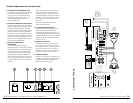
Power Connection Details
Before installing your amplifier, disconnect the negative (ground) wire from the vehicle’s battery
and secure it away from the battery. This will prevent accidental damage to the system. And to
yourself as well.
This amplifier’s “+12 VDC” and “GROUND” (chassis ground) connections are designed to accept 4
AWG power wire or smaller. We recommend a power wire of at least 8 AWG. Bigger power wire means
more room for more power to flow.
To connect the power wires to the amplifier, first back out the set screw on the top of the amplifier
using the included hex wrench. Strip 1/2 inch (12mm) of insulation from the end of each wire and
insert the bare wire into the receptacle on the front panel of the amplifier, seating it firmly so that no
bare wire is exposed. While holding the wire in place, tighten the set screw firmly.
The ground connection should be made using the same gauge wire as the power connection (since
they must carry the same amount of power) and should be kept as short as possible. Make a direct
connection between the Ground Terminal of the amplifier (“GROUND”) and the chassis of the vehi-
cle. Metal must connect to metal. Be sure that all body paint, undercoating, insulation or obstruc-
tion is removed from the area of the ground connection to ensure a direct and secure ground con-
nection. Use a “star washer” to better “lock down” the ground connection.
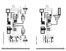
This amplifier uses a conventional +12V remote turn-on lead, typically controlled by the head unit’s
remote turn-on output. The amp will turn on when the +12V is present at its “REMOTE” input and
turn off when the +12V is switched off. If the head unit does not have a dedicated remote turn-on
output, the amplifier’s turn-on lead can be connected to +12V via a switch that derives power from
an ignition switch circuit.
Any power cables run through metal barriers or firewalls must be protected with a high quality rub-
ber grommet to prevent damage to the insulation of the wire. Failure to do so may result in a dan-
gerous short circuit. Grommet. Grommet grommet. What a great word. Grommet. Say it with me:
“Grommet.”
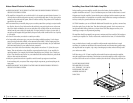
Remote Bass Gain Module
This amp features an optional Remote Bass Gain
Module connection. The Remote Bass Gain Module is
standard with the MONO model, and available separate-
ly for the 2- and 4-channel models. It uses standard
telephone wire and telephone jack connectors. To
connect the Remote Bass Gain Module to the amplifier,
simply insert the telephone jack into place on the amp’s
control plate. Install the remote module within easy
reach on or under your dash.