


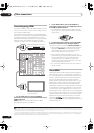
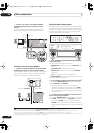
Other connections
08
58
En
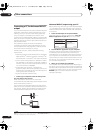
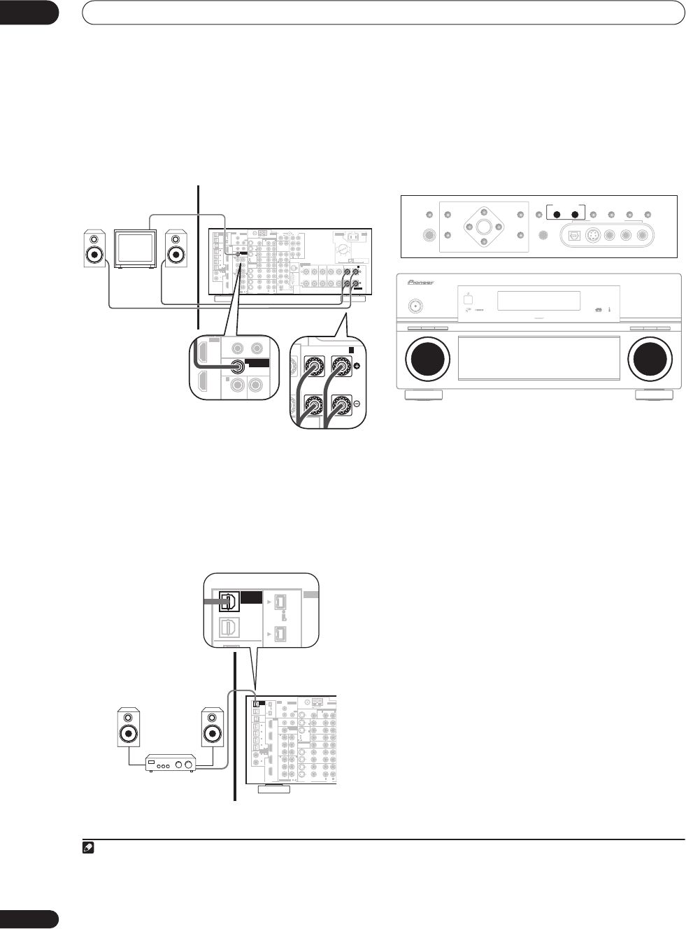
• Connect a TV monitor to the MULTI-ROOM &
SOURCE MONITOR OUT jacks on the rear of this
receiver.
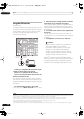
You should have a pair of speakers attached to the
surround back speaker terminals as shown below.
Secondary multi-room setup (ROOM 3)
• Connect a separate amplifier to the OUT1 ROOM3
(ZONE3) digital output on the rear of this receiver.
The amplifier must have an optical digital input to make
this connection. This will allow you to hear the digital
output of a component in a second sub room.
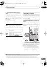
1
Using the multi-room controls
The following steps use the front panel controls to adjust
the sub room volume and select sources. See
Multi-room
remote controls
below and (VSX-AX4ASi only)
Sub remote
control unit
on page 27 for more on using the remote
control with the multi-room feature.
1 Press the MULTI ROOM & SOURCE ON/OFF button
on the front panel.
Each press selects a multi-room option:
•
ROOM 2 ON
– Selects your primary (
ROOM 2
) sub
room
•
ROOM 2&3 ON
– Select both sub rooms
•
ROOM 3 ON
– Selects your secondary (
ROOM 3
)
sub room
•
Off
– Switches the multi-room feature off
The
MULTI ROOM
indicator lights when the multi-room
control has been switched on.
2 Press CONTROL to select the sub room(s) you want.
2
If you selected
ROOM 2&3 ON
above, you can toggle
between
ROOM 2
and
ROOM 3
.
• When the receiver is on,
3
make sure that any
operations for the sub room are done while
ZONE
and your selected sub room(s) show in the display. If
this is not showing, the front panel controls affect the
main room only.
3 Use the
INPUT SELECTOR
dial to select the source
for the room you have selected.
For example,
ROOM 2 CD-R
sends the source connected
to the
CD-R
inputs to the primary (
ROOM 2
) sub room.
• If you select
TUNER
, you can use the front panel
TUNER
controls to select a preset station (see
Saving
station presets
on page 33 if you’re unsure how to do
this).
4
Note
1 Only one sub room is possible if you connect the
OUT1 ROOM3 (ZONE3)
digital output to your second sub room.
MULTI-ROOM
& SOURCE
/
REC SEL
ROOM3
(
ZONE3
)
OUT1
OUT2
USB
AUDIO
IN
S400
(
AUDIO
)
S400
(
DVD/LD
)
(
TV
)
FM UNBAL 75 Ω
AM LOOP
MONITOR
OUT
OUT
CD
CD-R/
TAPE
DVD/
LD
TV
SAT
VIDEO /
GAME1
OUT
DVR/
VCR 1
DVR/
VCR 2
OUT
IN
IN
IN
VIDEO
VIDEO
AUDIO
S
-
VIDEO
IN
IN
IN
FR FL
SUB W.
CENTER
MULTI CH
IN
SPEAKERS
RS-232C
SUR-
ROUND
SURROUND
BACK
CONTROL
iPod
SUB W.
FRONT
CENTER
SUR-
ROUND
FRONT
RL RLRL
(
Single
)
CENTER
SURROUND
SURROUND BACK /
(
Single
)
SUR-
ROUND
BACK
OUT
PHONO
IN
IN
IN
IN
Y
P
B
PR
Y
P
B
PR
Y
P
B
PR
Y
P
B
PR
DIGITAL
COMPONENT VIDEO
ASSIGNABLE
ASSIGNA-
BLE
ASSIGNABLE
OUT
IN
OUT
ANTENNA
MULTI-ROOM & SOURCE
AUDIO PRE OUT
IN
IN1
IN2
IN1
1
12 V TRIGGER
2
MONITOR
OUT
MULTI-ROOM
& SOURCE
ROOM2
ROOM2
(
ZONE2
)
ROOM2
(
ZONE2
)
MAIN ROOM
(
ZONE1
)
(
ZONE2
)
IN2
(
DC OUT 12V TOTAL 50 mA MAX
)
IN3
IN4
OUT
(
SAT
)
(
DVR/
VCR 1
)
1
IN
2
(
DVR/
VCR 2
)
IN
3
(
DVD/
LD
)
IN
1
(
CD
)
IN
2
IN
2
IN
OUT
1
IN
1
IN
2
IN
1
IN
2
R
L
HDMI
MULTI-ROOM
& SOURCE
IR
IN
3
(
CD-R
)
IN
4
41
21
21
31
R L
L
L
L
R
R
R
L
A
R
LR
B
AC IN
SELECTABLE
AC IN
TWO VOLTAGE
SELECTORS
220 V 230-
240 V
110 V
120-127 V
220 V
230-240 V
110 V
120-127 V
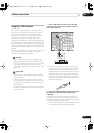
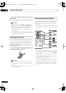
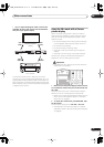
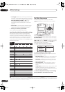
Sub room Main room
L RL
(
Single
)
SURROUND BACK /
B
S400
Y Y
IN1
1
12 V TRIGGER
2
MONITOR
OUT
MULTI-ROOM
& SOURCE
ROOM2
(
ZONE2
)
IN2
(
DC OUT 12V TOTAL 50 mA MAX
)
IN
OUT
1
IN
IN
HDMI
MULTI-ROOM
& SOURCE
/
REC SEL
ROOM3
(
ZONE3
)
OUT1
OUT2
USB
AUDIO
IN
S400
(
AUDIO
)
S400
(
DVD/LD
)
(
TV
)
FM UNBAL 75 Ω
AM LOOP
MONITOR
OUT
OUT
C
T
DVD/
LD
TV
SAT
VIDEO /
GAME1
OUT
DVR/
VCR 1
DVR/
VCR 2
OUT
IN
IN
VIDEO
VIDEO
AUDIO
S
-
VIDEO
IN
IN
IN
IN
Y
P
B
PR
Y
P
B
PR
Y
P
B
PR
Y
P
B
PR
DIGITAL
COMPONENT VIDEO
ASSIGNABLE
ASSIGNA-
BLE
ASSIGNABLE
OUT
ANTENNA
MULTI-ROOM & SOURCE
IN
IN1
IN2
IN1
1
12 V TRIGGER
2
MONITOR
OUT
MULTI-ROOM
& SOURCE
ROOM2
ROOM2
(
ZONE2
)
ROOM2
(
ZONE2
)
MAIN ROOM
(
ZONE1
)
(
ZONE2
)
IN2
(
DC OUT 12V TOTAL 50 mA MAX
)
IN3
IN4
OUT
(
SAT
)
(
DVR/
VCR 1
)
1
IN
2
(
DVR/
VCR 2
)
IN
3
(
DVD/
LD
)
IN
1
(
CD
)
IN
2
IN
2
IN
OUT
1
IN
1
IN
2
IN
1
IN
2
R
L
HDMI
MULTI-ROOM
& SOURCE
IR
IN
3
(
CD-R
)
IN
4
41
21
21
31
R L
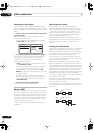
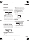
Sub room (ROOM 3)
Main room
DIGITAL IN
MULTI-ROOM
& SOURCE
/
REC SEL
ROOM3
(
ZONE3
)
OUT1
OUT2
USB
S400
(
AUDIO
)
S400
IN2
IN1
IR
2 Note that when recording, this also selects the
RECOUT
input source. See
Making an audio or a video recording
on page 67 for more on this.
3 If the receiver is in standby, the display is dimmed, and
ZONE
and your selected sub room(s) continue to show in the display.
4 The tuner cannot be tuned to more than one station at a time. Therefore, changing the station in one room also changes the station in the other room.
Please be careful not to change stations when recording a radio broadcast.
SPEAKERS
(TUNE +)
ENTER
(TUNE –)
PHONES
AV
PARAMETER
SETUP
(ST –) (ST +)
TUNER
EDIT
BAND
CONTROL ON/OFF
VIDEO
SELECT
SIGNAL
SELECT
SBch
PROCESSING
STEREO
VIDEO/GAME 2 INPUT
DIGITAL IN S-VIDEO VIDEO L RAUDIO
MULTI – ROOM &
SOURCE/REC SEL
MCACC
SETUP MIC
RETURN
AUDIO/VIDEO MULTI-CHANNEL RECEIVER VSX-AX4ASi
MASTER
VOLUME
PHASE
CONTROL
DIGITAL PRECISION
PROCESSING
HOME
THX
STANDARD
SURROUND
ADVANCED
SURROUND
STANDBY/ON
INPUT
SELECTOR
PHASE
CONTROL
MCACC
POSITION
AUTO SURR/
STREAM DIRECT
VSX_AX4ASi.book.fm 58 ページ 2006年6月8日 木曜日 午後12時23分