


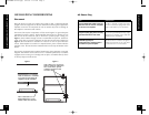
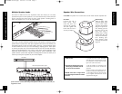


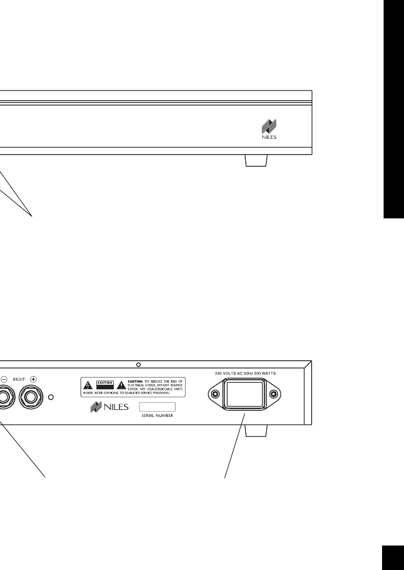
Binding posts for speaker
connections.
IEC receptacle for AC
power cord.
FRONT AND REAR PANEL DETAILS
10
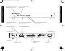
Red “Power” LED confirms the amplifier is
connected to a live AC power outlet. (and
that the master power switch is on).
Green “Active” LED lights when the
amplifier circuitry has been turned on by
the Turn-On circuits.
Front panel “Master Power” switch turns
off the entire amplifier, including the
Turn-On circuitry.
The red “Protect” LED indicates the amp has shut
down because there is a fault in a speaker, the
wiring, or with the SI-245 itself.
Level Adjustment screws enable you to preset
the maximum system volume (or match levels
with another amplifier).
Main Inputs enable you to route a stereo
line level source to the SI-245.
Cascade Outputs of the Main Input enable
you to daisy chain multiple amplifiers.
3.5mm Mini Plug socket for
12v DC Control output.
"Turn-On Mode" switch
3.5mm Mini Plug socket
for voltage input.
9
FRONT AND REAR PANEL DETAILS
NOTE: AC receptacle
must be easily accessible.
DS00284BMY-SI-245.qxp 6/27/05 2:14 PM Page 9