


47
<DRC1184>
En
English
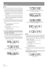
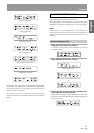
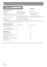
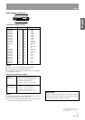
SCSI connector specifications
1) Pin layout of SCSI connectors
NOTES:
Pin No. 12 to 14, 37 and 39 are not grounded.
The connectors are of the shielded type.
For details on the control commands, refer to the separate
specifications manual.
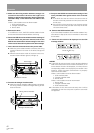
2) Electrical specifications of SCSI
NOTES:
As the SCSI interface is of the single-ended type, it should
be terminated on both ends of the cable.
The maximum recommended length of an SCSI cable is 6
meters (20 feet) (including internal wiring).
1
¡
±
+
Maintenance
In order to ensure safe and proper functioning of this unit,
we recommend regular maintenance. Extended service
life can be expected if maintained properly.
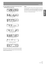
The signals driven by SCSI equipment present
the following input characteristics.
True (LOW): VOL = 0.0 to 0.4 V DC
IOL = -0.4 mA (0.4 V DC) max.
False (HIGH): VOH = 2.0 to 5.25 V DC
Input
characteristics
The signals driven by SCSI equipment
present the following output characteristics.
True (LOW): VOL = 0.0 to 0.4 V DC
IOL = 48 mA (0.5 V DC) max.
False (HIGH): VOH = 2.5 to 5.25 V DC
Output
characteristics
Published by Pioneer Corporation.
Copyright © 2002 Pioneer Corporation.
All rights reserved.
Signal name Pin No. Signal name
GROUND
GROUND
GROUND
GROUND
GROUND
GROUND
GROUND
GROUND
GROUND
GROUND
GROUND
NC
NC
NC
GROUND
GROUND
GROUND
GROUND
GROUND
GROUND
GROUND
GROUND
GROUND
GROUND
GROUND
26
27
28
29
30
31
32
33
34
35
36
37
38
39
40
41
42
43
44
45
46
47
48
49
50
1
2
3
4
5
6
7
8
9
10
11
12
13
14
15
16
17
18
19
20
21
22
23
24
25
-DB(0)
-DB(1)
-DB(2)
-DB(3)
-DB(4)
-DB(5)
-DB(6)
-DB(7)
-DB(P)
GROUND
GROUND
NC
TERMPWR
NC
GROUND
-ATN
GROUND
-BSY
-ACK
-RST
-MSG
-SEL
-C/D
-REQ
-I/O
Others