


5
ENGLISH
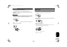
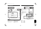
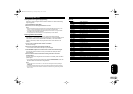
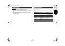
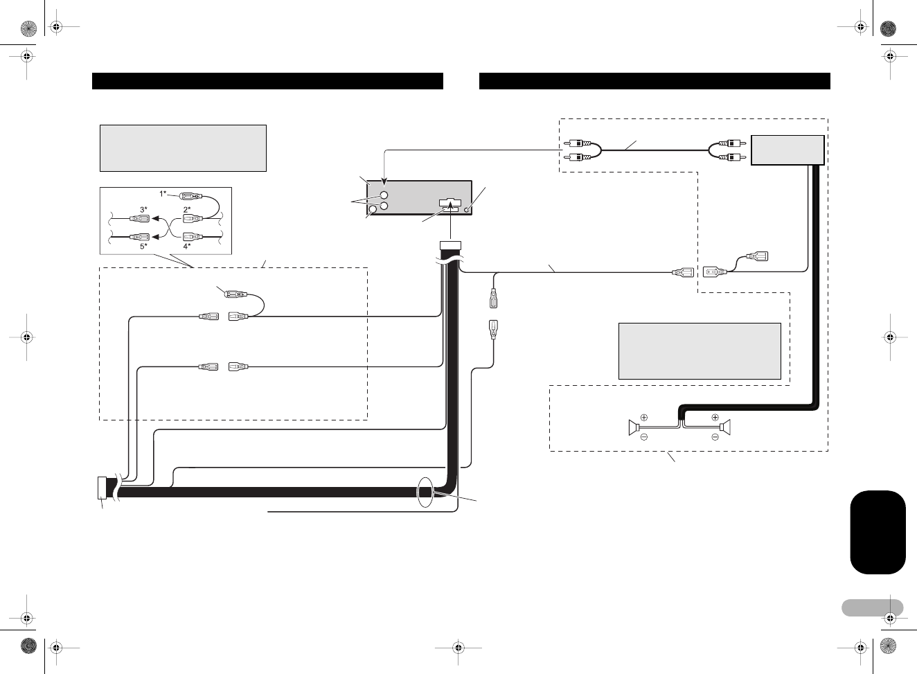
Connecting the Units
Note
Depending on the kind of vehicle, the
function of 3* and 5* may be different. In this
case, be sure to connect 2* to 5* and 4* to 3*.
Connect leads of the same
color to each other.
Cap (1*)
Do not remove cap if this
terminal is not in use.
Yellow (3*)
Back-up (or accessory)
Yellow (2*)
Connect to the constant 12 V supply
terminal.
Red (5*)
Accessory (or back-
up)
Red (4*)
Connect to terminal controlled by
ignition swich (12 V DC).
Black (chassis ground)
Connect to a clean, paint-free metal location.
ISO connector
Note
In some vehicles, the ISO connector may
be divided into two. In this case, be sure
to connect to both connectors.
Blue/white (6*)
Blue/white (7*)
Connect to auto-antenna relay control
terminal (max. 300 mA 12 V DC).
Blue/white
Connect to system control terminal of the
power amp (max. 300 mA 12 V DC).
Antenna jack
Speaker leads
White: Front left +
White/black: Front left -
Gray: Front right +
Gray/black: Front right -
Green: Rear left +
Green/black: Rear left -
Violet: Rear right +
Violet/black: Rear right -
Fuse
(10 A)
Yellow/black
If you use an equipment with Mute
function, wire this lead to the Audio
Mute lead on that equipment. If not,
keep the Audio Mute lead free of any
connections.
This product
Rear output
The pin position of the ISO connector will
differ depends on the type of vehicle.
Connect 6* and 7* when Pin 5 is an
antenna control type. In another type of
vehicle, never connect 6* and 7*.
Wired remote input
Hard-wired remote control adaptor can
be connected (sold separately).
System remote control
Connect with RCA cables
(sold separately)
Power amp (sold
separately)
Perform these connections when using
the optional amplifier.
Left Right
Rear Speaker Rear Speaker
MAN-DEH-3900MP-GB.fm Page 5 Monday, January 15, 2007 3:45 PM