


8
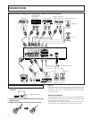
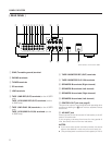
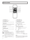
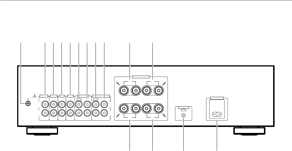
[ REAR PANEL ]
1 GND (Turntable ground) terminal
2 PHONO terminals
3 TUNER terminals
4 CD terminals
5 LINE terminals
6 TAPE 1/MD REC (OUT) terminals (on the A-307R
only)
TAPE 1/CD-R/MD REC (OUT) terminals (on the
A-209R only)
7 TAPE 1/MD PLAY (IN) terminals (on the A-307R
only)
TAPE 1/CD-R/MD PLAY (IN) terminals (on the
A-209R only)
8 TAPE 2 MONITOR REC (OUT) terminals
9 TAPE 2 MONITOR PLAY (IN) terminals
0 SPEAKERS B terminals (Right channel)
- SPEAKERS B terminals (Left channel)
= SPEAKERS A terminals (Right channel)
~ SPEAKERS A terminals (Left channel)
! CONTROL OUT jack (see page 5)
This jack is for output of control signals when operating other
components bearing the Î mark with the attached remote
control unit.
@ AC INLET jack
Connect power cord to here and an AC wall socket, or the AC
outlet of an audio timer.
If you are going to be away from home for a long period of
time, disconnect the unit from the wall socket.
NOTES:
÷
If you use an other power cord than provided, we cannot
assume the liabilities in what may occur as a result of it.
÷
(The provided power cord has a current capacity of 2.5 A.)
SIGNAL
GND
L
R
PHONO
IN
TUNER
IN
CD
IN
LINE
IN
TAPE 1/MD
REC PLAY REC PLAY
OUT INOUT IN
L
R
SPEAKERS
AC INLET
CONTROL
OUT
RL
R
A
B
L
1 0 -2 3 4 65 7 8 9
!~= @
TAPE 2 MONITOR
ª
·
ª
·
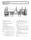
PANEL FACILITIES
The illustration shows the A-307R.