


PFAM550
6
Rev. 07/03
Ph: 800-421-6511
www.picomacom.com
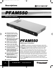
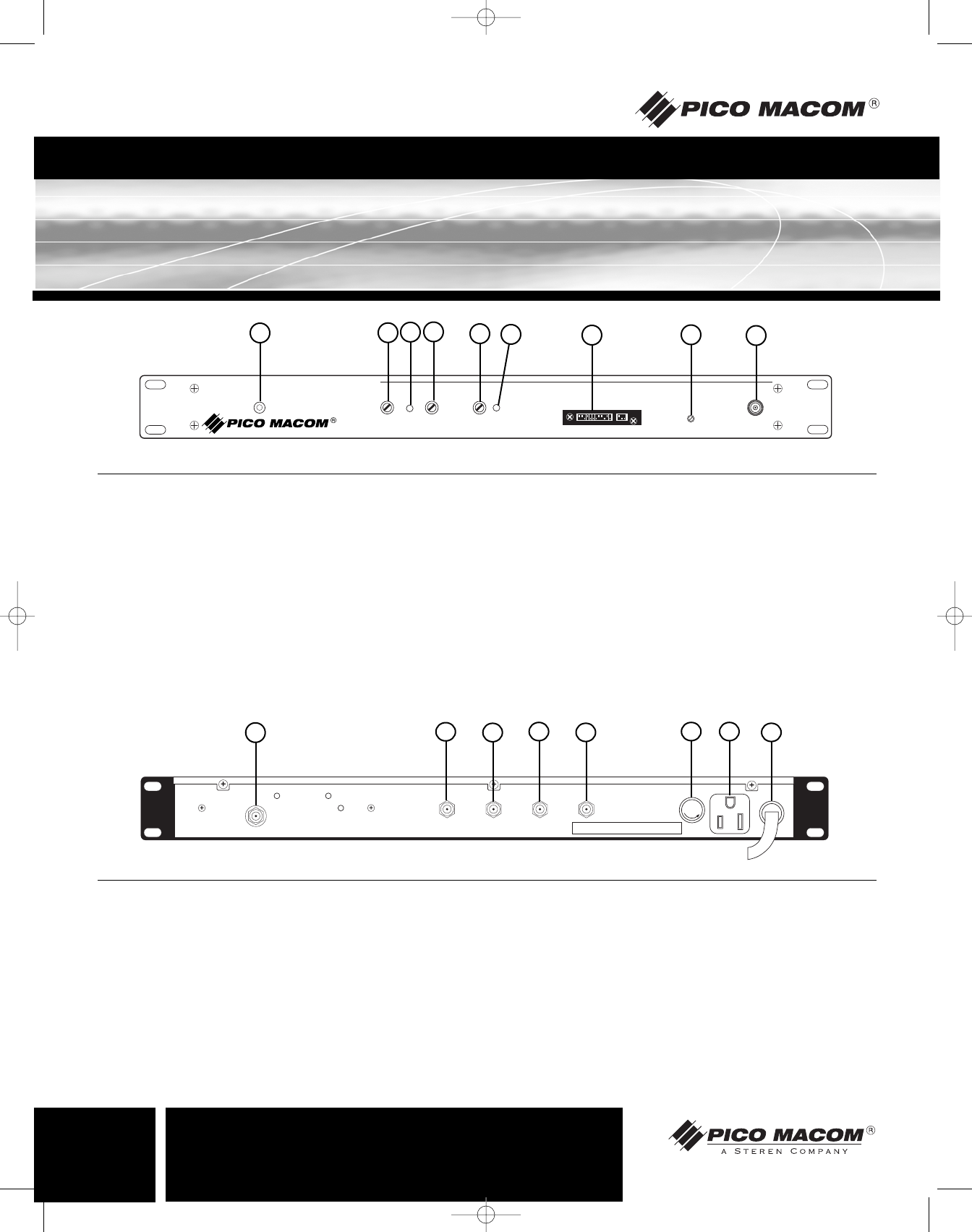
Operation and Controls
POWER
550MHz Agile A/V Modulator
PFAM550
VIDEO/
AUDIO
RATIO
AUDIO
OVER
MOD.
AUDIO
MOD.
VIDEO
MOD.
CHANNEL
RF LEVEL
TEST POINT
-30dB
VIDEO
OVER
MOD.
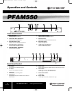
1. Power On LED:
Indicates power is on when lit.
2. Video/Audio Ratio Adjustment:
Used to set level of audio carrier.
3. Audio Modulation LED:
Indicates aural over modulation level when lit.
4. Audio Modulation Adjustment:
Used to set audio modulation (Volume).
5. Video Modulation Adjustment:
Used to set video modulation.
6. Video Modulation LED:
Indicates video over-modulation when lit.
7. Channel Select:
Dip switches are used to select desired channel.
8. RF Output Adjust:
Used to set output level.
9. -30dB Output Test Monitor:
Used to monitor RF output level.
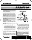
Front Panel Control
RF OUT
IF IN IF OUT VIDEO IN AUDIO IN
AC117V
60Hz/35W
600W MAX
125VAC
0.5A
CAUTION:
FOR CONTINUED PROTECTION AGAINST FIRE
HAZARD, REPLACE ONLY WITH SAME TYPE 0.5A 125V FUSE
FUSE
1. RF Output:
Connect this port to distribution system.
2. I.F. Input:
Input from I.F. scrambler or I.F. output.
3. I.F.Output:
To I.F. input or to scrambling device.
4. Video Input:
Accepts video output from satellite receiver, VCR and
CCTV camera.
5. Audio Input:
Accepts audio output from satellite receiver, VCR and CCTV camera.
6. Fuse holder:
117VAC type - 0.5 amp, 125V slow-blow fuse.
220VAC type - 0.5 amp, 250V slow-blow fuse.
7. Convenience Outlet:
117VAC type
8. Power Cord:
117VAC type - Three wire, standard U.S.A. type.
Back Panel Control
1
2
3
4
5
6
7
8
9
1
2
3
4
5
6 7
8
PFAM550 Manual.qxd 7/29/03 2:11 PM Page 6