


PCFM
6
Rev. 07/03
Ph: 800-421-6511
www.picomacom.com
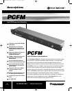
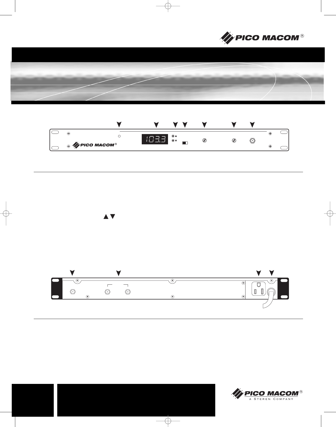
Operation and Controls
Agile FM Stereo Audio Modulator
PCFM
FREQ.
MONO STEREO
AUDIO MODULATION
TEST POINT
-20 DB
R.F OUT
POWER
1
2
3 4 5
6
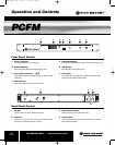
1. Power Indicator:
The LED indicates unit is operating.
2. Station Display:
Seven-segment display indicates FM frequency.
3. Freq. Select Controls:
Push these buttons to change channel to higher or lower
frequency.
4. Mono/Stereo:
Slide switch selects mono or stereo modes.
5. Audio Modulation:
The audio modulation level (loudness) is set with this control.
6. RF Output:
The RF level is set with this control.
7. Test Point:
The -20 dB RF output test point is used to set the RF output
level and monitor station performance.
Front Panel Control
RF OUT
120VAC
60Hz 10W
AUDIO IN
600W MAX
L
R
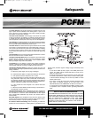
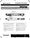
1. RF Out:
Connect this port to the distribution system.
2. Audio In:
Connect a 1 V p-p (2 V p-p max.) mono or stereo signal
source from a satellite receiver or VCR.
4. Convenience Outlet:
Allows looping of power between units.
5. Power Cord:
The three-prong type power plug connects to a 120 VAC,
60 Hz electrical outlet.
Back Panel Control
1
2 3
4
7
PCFM Manual.qxd 7/10/03 1:14 PM Page 6