


PICO MACOM INC.
12500 Foothill Blvd., Lakeview Terrace, CA 91342 • (818) 897-0028 • (800) 421-6511 • FAX (818) 834-7197
P A N E L S
4
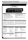
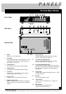
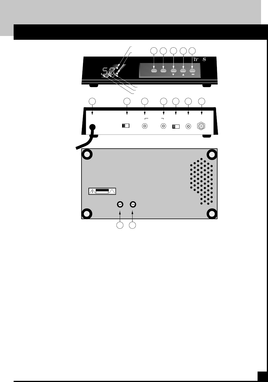
Front & Rear Panels
1. Offset:
Selects 12.5 or 25 kHz offset.
2. Ch. Mode:
Selects Standard, HRC or IRC frequencies. Set in
standard position unless your cable company re-
quires HRC or IRC offset.
3. Channel Select:
Press button to select lower channel number
4. Channel Select:
Press button to select higher channel number.
5. CATV/TV
Selects cable or off-air modes. "Dot" appears
on display when in CATV mode.
6. Power Cord:
Connect to 120 Vac, 60Hz electrical outlet.
7. Display on/off switch:
Set this switch to on to illuminate seven segment
display on front panel and to activate front panel
controls.
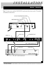
Front Panel
Rear Panel
Bottom Panel
8. Right Audio In:
Accepts a balanced audio output from satellite
receiver, VCR, cable converter, etc.
9. Left Audio and Baseband In:
Accepts a balanced audio output from satellite
receiver, VCR, cable converter, etc.
10. Left Audio/Base Band Select:
If stereo sound is desired a BTSC stereo generator
must be used. Set slide switch to B.B. and connect
left audio to the composite out of the generator.
See page 6.
11. Video Input:
Accepts video output from satellite receiver , VCR
or cable converter.
12. RF Out:
To TV or distribution system.
13. Video Adjust:
Used to set video modulation level. Adjust for
best picture.
14. B.B. Adjust:
Used to set audio modulation level.
Adjust for desired sound level.
VIDEO
IN
AUDIO IN
RF
OUT
DIP.
OFF ON
R
L/B.B.
8 9 10 11 12
345
6 7
AC120V
60Hz
15W
+
++
+
VIDEO
ADJUST
1413
B.B.
ADJUST
!
CAUTION
RISK OF ELECTRIC SHOCK
DO NOT OPEN
L B.B.
12
CHANNEL
OFFSET
CATV/TV
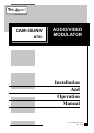
CAM-35UNIV
•
™
®
pec
u
PICO MACOM INC.
CH
MODE
25kHz
1.25kHz
STD
HRC
IRC