


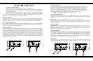


6. BRIDGED OPERATION
The STEREO/MONO switch is located just behind the input panel. This switch is used to select between
NORMAL STEREO operation, DUAL MONO operation, or BRIDGED MONO operation. For NORMAL
STEREO operation, use CH 1 and CH 2 inputs. For DUAL MONO or BRIDGED MONO operation, use CH
2 input only (see page 12 for instructions on how to access the Stereo/Mono switch, and page 8 for more
information about Bridged Operation).
7. LEVEL DEFEAT SWITCH
Locks the amplifier at its full gain capacity (see page 12 for more information).
8. SEQUENCE SND/RCV
These barrier strip screw terminals are used to link multiple amplifiers for sequenced turn-on. Connect the
SND (SEND) terminal of the first amplifier to the RCV (RECEIVE) terminal of the second amplifier.
Connect the SND terminal of the second amplifier to the RCV terminal of the third amplifier, and so on (see
page 9 and 10 for more information on Power ON sequencing).
9. CLIPPING ELIMINATOR SWITCH
The Clipping Eliminator circuit can be activated with a switch located to the right of the input panel. Moving
the switch down will deactivate the Clipping Eliminator, allowing the amplifier to clip when driven beyond
its maximum output capability. (See page 9 for additional information on the clipping eliminator circuit.)
10. CH1 / CH2 INPUT CONNECTORS
There are two methods for making input connections to the amplifier. 1/4-inch TRS (Tip-Ring-Sleeve)
connections are provided as well as professional XLR connectors. They can be used with balanced signals
or unbalanced signals (see Input Wiring on page 7 for more information).
Note: A high-quality input transformer option is available for the pm1400 power amplifiers. Contact your
Carver Professional Dealer for details.
11. FAN EXHAUST
This opening releases hot air from inside the amplifier. Be sure this vent is clear of obstructions for maximum
cooling efficiency.
12. CH1 / CH2 SPEAKER OUTPUTS
Multi-way binding posts are used to connect the loudspeakers to the amplifier outputs. The red terminals are
the signal connection (+) and the black terminals are the signal return connection (–). The black terminals
are internally tied together and to signal ground.
13. POWER CORD
Connect to a properly configured outlet providing the line voltage specified for your model.
TO REDUCE THE RISK OF FIRE OR ELECTRIC SHOCK,
DO NOT EXPOSE THIS EQUIPMENT TO RAIN OR MOISTURE.
WARNING
120 VAC
50-60 Hz
CLASS 1 WIRING
SHALL BE USED
MADE
IN
USA
+
–
GND
FOR BRIDGED
OPERATIONS CONSULT
OWNER'S MANUAL
ENERGIE ELECTRIQUE DANGEREUSE.
VOIR LA INOTICE DE FONCTIONNEMENT.
AVERTISSEMENT
RISK OF HAZARDOUS ENERGY! MAKE PROPER
SPEAKER CONNECTIONS. SEE OPERATING
MANUAL BEFORE USING.
WARNING
1
2
3
+
Serial Number
12
3
PUSH
12
3
PUSH
INPUT IMPEDANCE 25K OHMS EACH LEG TO GROUND (TOTAL 50K OHMS BALANCED)
SEQUENCE
SND RCV
ON
CAUTION ATTENTION
RISQUE DE CHOC ELECTRIQUE
NE PAS OUVRIR
RISK OF ELECTRIC SHOCK
DO NOT OPEN
CLIPPING
ELIMINATOR
OFF
ON OFF
LEVEL DEFEAT
6 8
9
10 11 12 13
7
4
∞
∞
∞
2
1
4
5
3 4
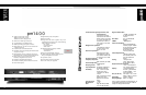
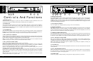
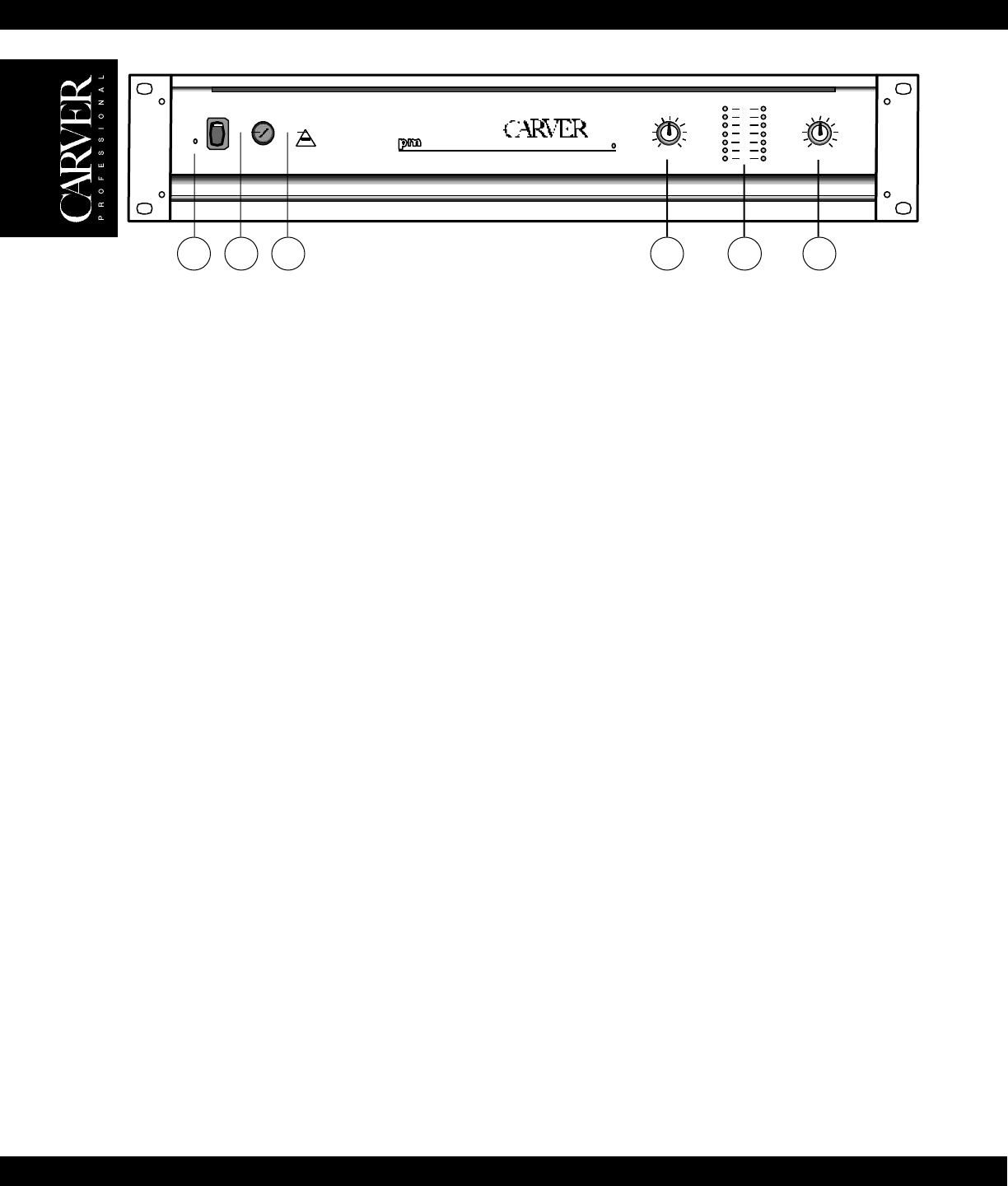
Controls And Functions
1. POWER SWITCH
When this switch is engaged, the power turns ON and the READY indicators illuminate. Be sure all
connections are made and double-checked before switching the power amplifier on.
2. STANDBY LED
This indicator illuminates when the power switch is turned OFF. It also lets you know when the amplifier is
connected to AC power. When the power switch is OFF and the amplifier is plugged into an AC outlet, the
LED illuminates to indicate that AC power is available and the amplifier can be powered up. When the power
switch is ON, the LED turns off.
3. AC POWER FUSE
This protects the amplifier from catastrophic failures that could damage internal circuitry. Repeated fuse
blowing is a sign of internal distress. See page 14 for information on authorized Carver Professional Service.
Caution: Always replace with the same type and value fuse indicated next to the fuseholder.
4. CH1 / CH2 LEVEL CONTROLS
These controls are used to adjust the input level of each channel. When the controls are fully clockwise the
amplifier operates at maximum gain. Turning the controls counter-clockwise attenuates the input signal. The
Level controls can be bypassed. See back panel for Level Defeat Switch.
Note: A precision attenuator is available as an option for the pm1400, which can be installed inside the
amplifier (see page 11). Contact your Carver Professional Dealer for details.
5. CH1 / CH2 STATUS INDICATORS
These LEDs display information about the operation of the amplifier.
READY – These LEDs illuminate green when the power is on and the amplifier is ready to operate. The
READY LEDs illuminate red when the power switch is first turned on (while the power supply is stabilizing
prior to the speaker output relays switching in), or when the amplifier is in protect mode.
SIGNAL – These LEDs illuminate yellow when a signal is present at the Speaker Output jacks to provide an
indication of output power relative to full power (0dB).
CLIP/PROTECT – These LEDs illuminate red when the power switch is first turned on, when the output
begins to clip, or whenever there is a fault condition detected that causes the output relay(s) to disengage.
These fault conditions include excessive DC Offset, excessive heatsink temperature and short circuits at the
speaker output(s).
Note: The relays operate independently for each channel. Therefore, it is possible for one channel to operate
normally while the other is in “protect” mode.