


1998 July 30
Philips Semiconductors Objective Specification, Revision 2.2
Pre-Amplifier for Hard Disk Drive with
MR-Read / Inductive Write Heads
TDA5360
32
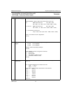
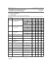
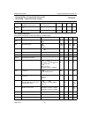
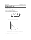
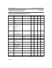
13 LIMITING VALUES / RECOMMENDED OPERATION CONDITIONS
In accordance with the Absolute Maximum System (IEC 134)
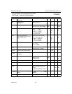
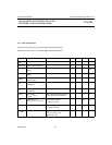
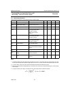
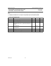
SYMBOL PARAMETER CONDITIONS MIN. TYP MAX. UNIT
V
CC
Positive Supply voltage
range
note1 4.5 5.0 5.5 V
V
EE
Negative Supply voltage
range
note 2 -4.5 - 5.0 -5.5 V
V
IH
High level CMOS input
voltage
2.4 V
CC
V
V
IL
Low level CMOS input
voltage
0 0.8 V
V
i(dif)(p-p)
(Writer input)
Differential Peak to Peak
input voltage
High level PECL input
voltage
Low level PECL input
voltage
0.4
2.4
0.7
3.2
2.8
1.5
V
CC
V
V
V
Imode
(Writer input)
Differential Peak to Peak
input current
High level input current
Low level input current
0.4
-1.4
0.8
-1.2
-0.4
1.0
-0.1
mA
mA
mA
T
amb
Ambient temperature 0 55 70 °C
T
j
Junction temperature when reading
when writing
70 110
130
°C
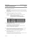
R
MR
MR element resistance 46 66 86 Ohm
L
l(tot)
Total lead inductance to
the head
in each lead - 17 nH
R
l(tot)
Total lead resistance to the
head
in each lead - 1.5 Ohm
V
MR
Voltage accross MR
element (RPx-RNx)
1 V
V
sig(dif)(p-p)
MR head input signal peak
to peak voltage
differential 0.4 1 3 mVpp
L
wh
Write Head inductance including lead 75 nH
R
wh
Write Head resistance including lead - 10 Ohm
C
wh
Write head capacitance including lead - TBD pF
R
ext
Reference resistor Iref=Vref/Rext 9.9 10 10.1 k Ω